10gbe simulation timing diagrams, 10gbe simulation timing diagrams –13 – Altera 10-Gbps Ethernet MAC MegaCore Function User Manual
Page 31
Chapter 3: 10GbE MAC Design Examples
3–13
10GbE Testbenches
February 2014
Altera Corporation
10-Gbps Ethernet MAC MegaCore Function User Guide
// Configure the RX FIFO
U_AVALON_DRIVER.avalon_mm_csr_wr(RX_FIFO_DROP_ON_ERROR_ADDR,RX_FIFO_DROP_ON_ERROR);
// Read the configured registers
U_AVALON_DRIVER.avalon_mm_csr_rd(RX_FIFO_DROP_ON_ERROR_ADDR, readdata);
$display("RX FIFO Drop on Error Enable = %0d", readdata[0]);
U_AVALON_DRIVER.avalon_mm_csr_wr(32'h948, 1)
4. Run the following command again to reconfigure the loopback module, set up the
required libraries, compile the generated IP Functional simulation model, and
exercise the simulation model:
do tb_run.tcl
r
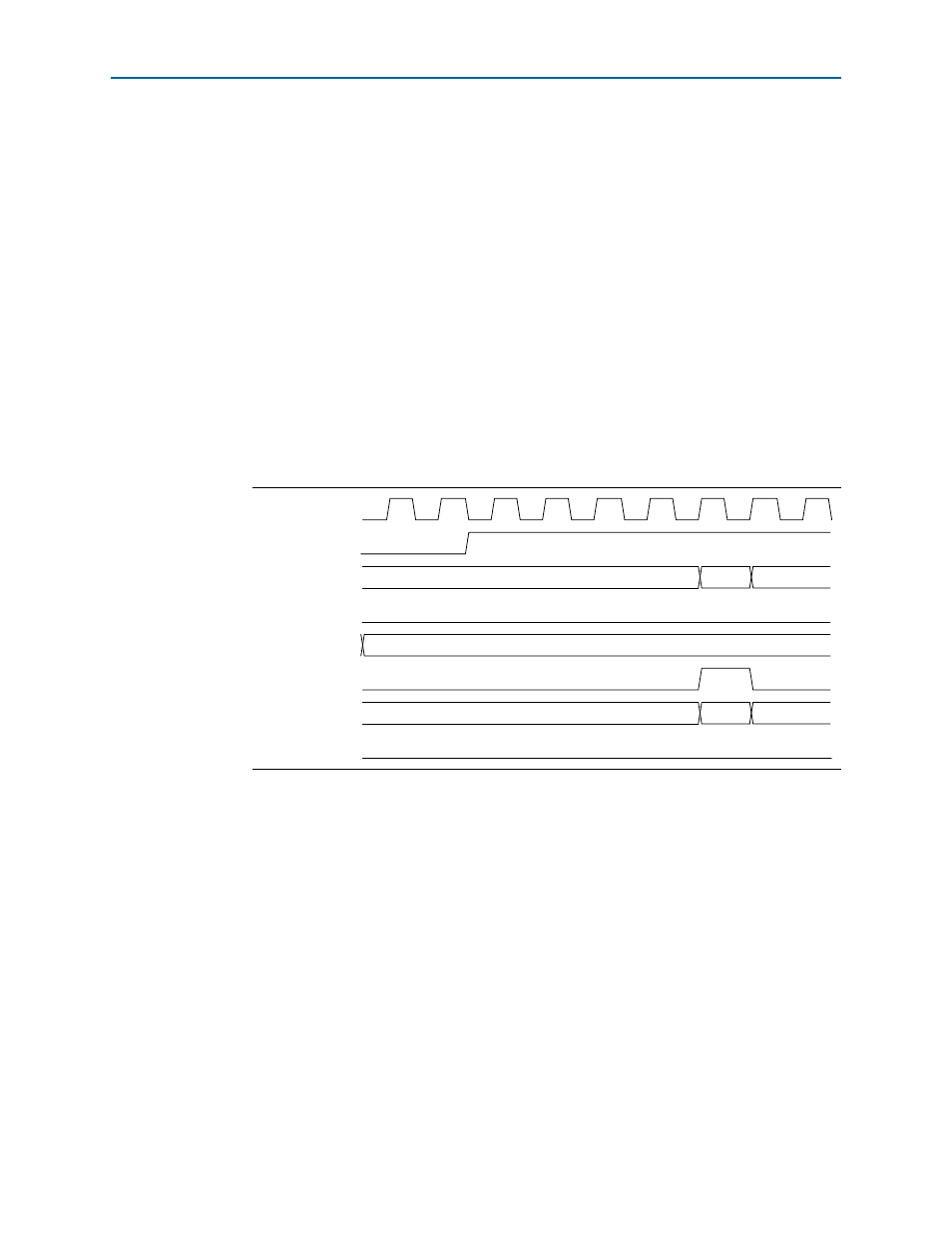
3.6.7. 10GbE Simulation Timing Diagrams
shows the reset and initial configuration sequence. The first read or write
transaction must be at least one clock cycle after the csr_reset_reset_n signal
completes.
Figure 3–4. Reset and Configuration
csr_clk_clk
csr_reset_reset_n
csr_address [18:0]
csr_read
csr_readdata [31:0]
csr_write
csr_writedata [31:0]
csr_waitrequest
40084
00000002