Altera Stratix V Avalon-ST User Manual
Page 54
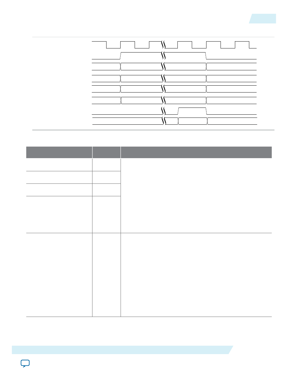
Figure 4-3: Timing Diagram for MSI-X Interrupt Generation
pld_clk
MSI-X Function No
MSI-X Address
MSI-X TC
app_msix_req
app_msi_req_fn[7:0]
app_msix_addr[63:0]
app_msi_tc[2:0]
app_msix_ack
MSI-X Data
app_msix_data[31:0]
app_msi_status[1:0]
Table 4-10: Legacy Interrupts
Signal
Direction
Description
app_int_sts_a
Input
The Application Layer uses this signal to generate a legacy
INT<x>
interrupt. <x> corresponds to a-d for functions
programmed to use interrupt pins a-d. The Hard IP sends an
INTx_Assert
message upstream to the Root Complex in
response to a low-to- high transition. The Hard IP sends a
INTX_
Deassert
in response to a high-to-low transition. The
INTX_
Deassert
message is only sent if a previous
INTx_Assert
message was sent.
and
diagrams.
This input has no effect if the
INT<x>Disable
bit in the PCI
Command Register of the interrupting function is set to 1.
app_int_sts_b
Input
app_int_sts_c
Input
app_int_sts_d
Input
app_int_ack
Output
A pulse on this output indicates that an
INTx_Assert
or
INTX_
Deassert
message has been sent. Assertion is in response to a
transition on a
app_int_sts_<x>
input. This signal is asserted for
at least 1 cycle when an
INTx_Assert
message TLP has been
transmitted. It is asserted when either of the following occurs:
• A low-to-high transition on one of the
app_int_sts_<x>
inputs
• A
INTX_Deassert
message TLP has been transmitted in
response to a high-to-low transition
The Application Layer must wait for
app_int_ack
the after
making a transition on one of the
app_int_sts_<x>
inputs,
before signaling a new transition.
UG-01097_sriov
2014.12.15
Interrupt Interface
4-19
Interfaces and Signal Descriptions
Altera Corporation