Transceiver reconfiguration – Altera Stratix V Avalon-ST User Manual
Page 64
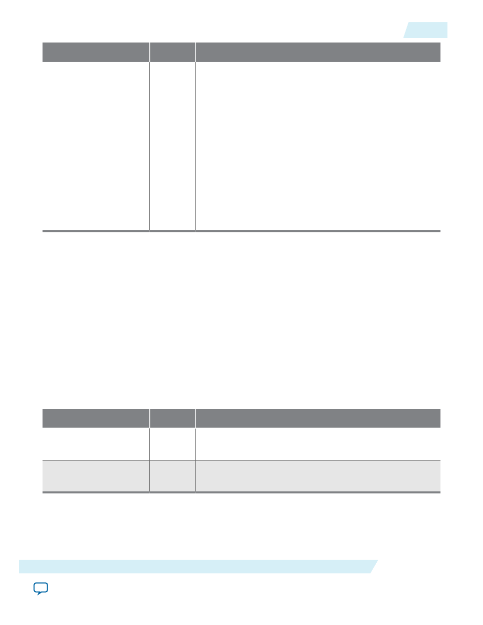
Signal
Direction
Description
tx_par_err[1:0]
Output
When asserted for a single cycle, indicates a parity error during
TX TLP transmission. These errors are logged in the VSEC
register. The following encodings are defined:
• 2’b10: A parity error was detected by the TX Transaction
Layer. The TLP is nullified and logged as an uncorrectable
internal error in the VSEC registers. For more information,
refer to Uncorrectable Internal Error Status Register.
• 2’b01: Some time later, the parity error is detected by the TX
Data Link Layer which drives 2’b01 to indicate the error.
Altera recommends resetting the Stratix V Hard IP for PCI
Express when this error is detected. Contact Altera if resetting
becomes unworkable.
Note that not all simulation models assert the Transaction Layer
error bit in conjunction with the Data Link Layer error bit.
Related Information
•
•
Transceiver Reconfiguration
Dynamic reconfiguration compensates for variations due to process, voltage and temperature (PVT).
Among the analog settings that you can reconfigure are V
OD
, pre-emphasis, and equalization.
You can use the Altera Transceiver Reconfiguration Controller to dynamically reconfigure analog
settings. For more information about instantiating the Altera Transceiver Reconfiguration Controller IP
core refer to Hard IP Reconfiguration .
Table 4-15: Transceiver Control Signals
In this table, <n> is the number of interfaces required.
Signal Name
Direction
Description
reconfig_from_
xcvr[(<n>46)-1:0]
Output
Reconfiguration signals to the Transceiver Reconfiguration
Controller.
reconfig_to_xcvr[(<n>
70)-1:0]
Input
Reconfiguration signals from the Transceiver Reconfiguration
Controller.
The following table shows the number of logical reconfiguration and physical interfaces required for
various configurations. The Quartus II Fitter merges logical interfaces to minimize the number of physical
interfaces configured in the hardware. Typically, one logical interface is required for each channel and one
for each PLL. The ×8 variants require an extra channel for PCS clock routing and control. The ×8 variants
use channel 4 for clocking.
UG-01097_sriov
2014.12.15
Transceiver Reconfiguration
4-29
Interfaces and Signal Descriptions
Altera Corporation