Msi-x capability structure – Altera Stratix V Avalon-ST User Manual
Page 82
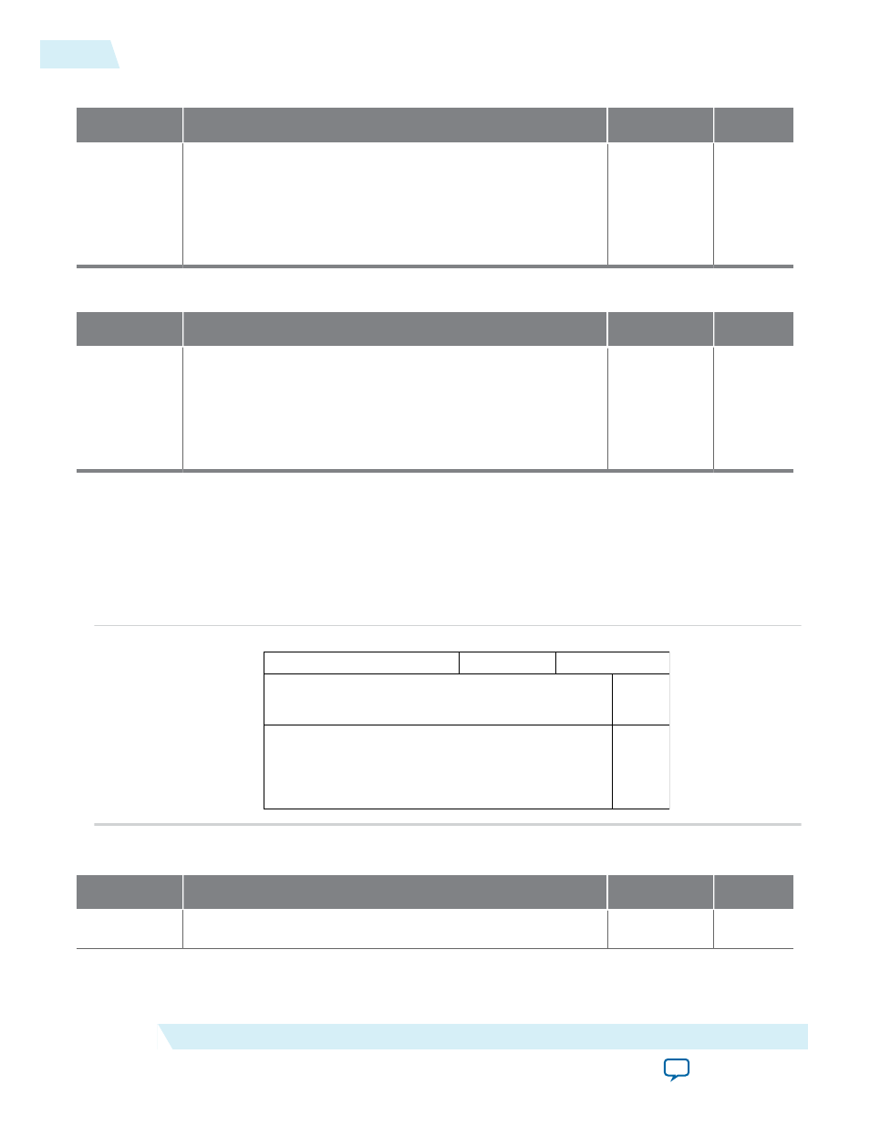
Table 5-7: MSI Mask Register - 0x05C (32-bit addressing) or 0x060 (64-bit addressing)
Bits
Register Description
Default Value
Access
31:0
Mask bits for MSI interrupts. The number of implemented bits
depends on the number of MSI vectors configured. When one
MSI vectors is used , only bit 0 is RW. The other bits read as
zeroes. When two MSI vectors are used, bits [1:0] are RW, and so
on. A one in a bit position masks the corresponding MSI
interrupt.
See description
0
Table 5-8: Pending Bits for MSI Interrupts Register - 0x060 (32-bit addressing) or 0x064 (64-bit addressing)
Bits
Register Description
Default Value
Access
31:0
Pending bits for MSI interrupts. A 1 in a bit position indicated the
corresponding MSI interrupt is pending in the core. The number
of implemented bits depends on the number of MSI vectors
configured. When 1 MSI vectors is used, only bit 0 is RW. The
other bits read as zeroes. When 2 MSI vectors are used, bits [1:0]
are RW, and so on.
RO
0
Related Information
MSI-X Capability Structure
Figure 5-3: MSI-X Capability Registers - Byte Address Offsets and Layout
0x068
0x06C
0x070
Message Control
Next Cap Ptr
MSI-X Table Offset
MSI-X Pending Bit Array (PBA) Offset
31
24 23
16 15
8 7
0
Capability ID
3 2
MSI-X
Table BAR
Indicator
MSI-X
Pending
Bit Array
- BAR
Indicator
Table 5-9: MSI-X Capability ID, Capability Pointer and Mask Register - 0x068
Bits
Register Description
Default Value
Access
[31]
MSI-X Enable. When set, enables MSI-X interrupt generation.
0
RW
5-8
MSI-X Capability Structure
UG-01097_sriov
2014.12.15
Altera Corporation
Registers