Pci express capability structure – Altera Stratix V Avalon-ST User Manual
Page 85
PCI Express Capability Structure
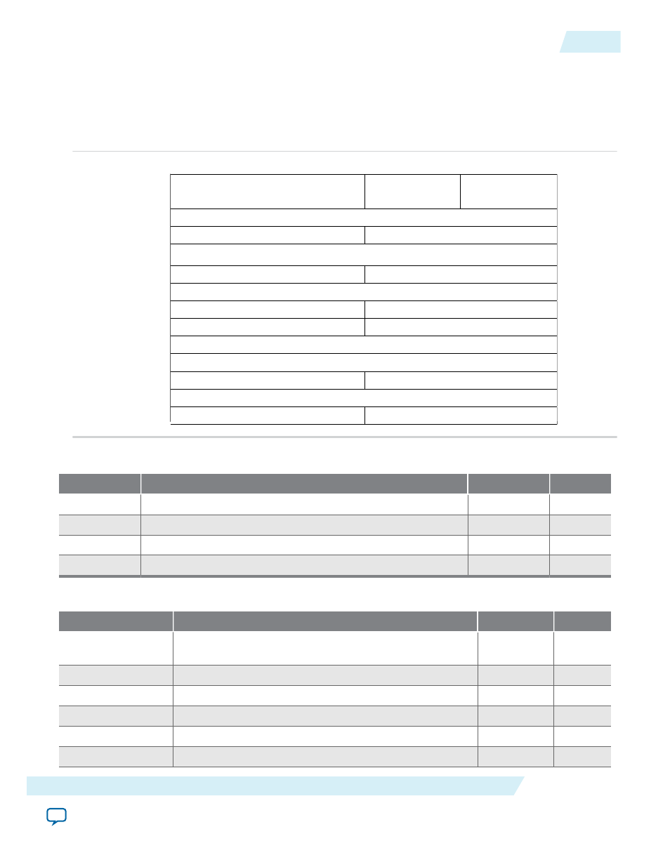
Figure 5-5: PCI Express Capability Structure - Byte Address Offsets and Layout
In the following table showing the PCI Express Capability Structure, registers that are not applicable to a
device are reserved.
0x080
0x084
0x088
0x08C
0x090
0x094
0x098
0x09C
0x0A0
0x0A4
0x0A8
0x0AC
0x0B0
PCI Express Capabilities Register
Next Cap Pointer
Device Capabilities
Device Status
Device Control
Slot Capabilities
Root Status
Device Compatibilities 2
Link Capabilities 2
Link Status 2
Link Control 2
31
24 23
16 15
8 7
0
PCI Express
Capabilities ID
Link Capabilities
Link Status
Link Control
Slot Status
Slot Control
Device Status 2
Device Control 2
Root Capabilities
Root Control
Table 5-12: PCI Express Capability Register - 0x080
Bits
Description
Default Value
Access
[31:19]
Reserved
0
RO
[18:16]
Version ID: Version of Power Management Capability.
0x3
RO
[15:8]
Next Capability Pointer: Points to the PCI Express Capability.
0x80
RO
[7:0]
Capability ID assigned by PCI-SIG.
0x01
RO
Table 5-13: PCI Express Device Capabilities Register -0x084
Bits
Description
Default Value
Access
[2:0]
Maximum Payload Size supported by the Function. Can be
configured as 000 (128 bytes) or 001 (256 bytes)
Set in Qsys
RO
[4:3]
Reserved
0
RO
[5]
Extended tags supported
Set in Qsys
RO
[8:6]
Acceptable L0S latency
0
RO
[11:9]
Acceptable L1 latency
0
RO
[14:12]
Reserved
0
RO
UG-01097_sriov
2014.12.15
PCI Express Capability Structure
5-11
Registers
Altera Corporation