Exit end view – Rena T-650 User Manual
Page 9
GETTING ACQUAINTED
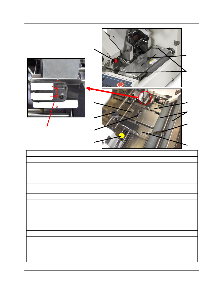
Exit End View
1
Head 1 Securing Knob – This knob is used to secure the position of Head 1.
2
Exit Foot Knob – This knob is used to adjust and secure the position of the exit foot.
3
Exit Roller Assembly Securing Latches – These latches are used to lock down the exit
roller assembly.
4
Right Media Guide Securing Knob – This knob is used to secure the position of the
right media guide assembly.
5
Front Tabbing Slot – This opening, located in the center support plate, is used when
applying tabs to the leading edge of the media (front tabbing).
6
Head Position Minder – Used to memorize the position of Head 1.
7
Media Hold-down Guide – Used to keep the media from lifting as it feeds through the
tabber. This guide is adjusted from the entrance end of the tabber.
8
Tab Wrap Guide – Left – When side-tabbing, this guide wraps the tab around the
media.
9
Exit Pressure Rollers – These rollers provide transport pressure to the media and seal
the tabs to the media.
10
Exit Foot – This device holds the media down as it travels under the exit rollers.
11
Tab Wrap Guide - Right – When side-tabbing, this guide wraps the tab around the
media.
12
Tab Applicator Assembly – This assembly contains the tab sensor. The notches,
located at the top and bottom edges of this assembly, provided a reference for the
position of the sensor. Each head (Head 1 and Head 2) includes a Tab Applicator Assy.
6
11
4
10
9
7
8
5
12
Sensor
Sensor
1
3
2
T-650 Operations REV. 8/25/2010
9