8 – troubleshooting and system tests, Figure 6 – Hypertherm Powermax125 Service Manua User Manual
Page 117
Powermax125 Service Manual 808070
117
8 – Troubleshooting and System Tests
3. Check the resistance from the input leads to ground to verify that it reads as open. For all power supplies, the
resistance from input to ground should read as > 20 MΩ.
With the power disconnected and the ON/OFF switch (S1) set to OFF (O), all circuits
should read as open.
The electrical values shown are ±50%. However, this range is intended only for reference.
Resistance values can vary widely depending on the type of multimeter and the polarity
used to measure the readings.
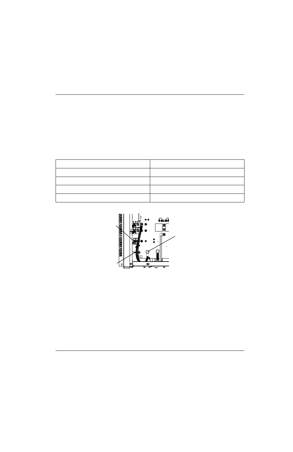
4. Check the output resistance for the values shown in the table.
Figure 6
If no problems were found during the visual inspection or the initial resistance check, and the power supply still does not
operate correctly, see the
Troubleshooting guide on page 143.
Troubleshooting guide on page 143 provides most probable causes and solutions.
Study the
Powermax125 schematic diagram on page 317 and understand the Theory of
operation on page 111 before troubleshooting. Before purchasing any major replacement
component, verify the problem with Hypertherm Technical Service or the nearest
Hypertherm repair facility.
Measure resistance from
All models with the torch removed
Work lead (J27) to nozzle (black wires)
230 kΩ
Work lead (J27) to electrode (red wire)
9 kΩ
Electrode (red wire) to nozzle (black wires)
230 kΩ
Output to ground (not shown)
>20 MΩ
J22
J21
J20
J19
J27
WORK
LEAD
J26
J25
+
_
+
_
RED
J18
ORG
J17
RED
J32
J28
C152
C151
TP7
TP9
TP8
W
R
B
Black wires (nozzle)
Red wire (J28)
Work lead (J27)