Sink. see, N figure 76 on – Hypertherm Powermax125 Service Manua User Manual
Page 215
Advertising
Powermax125 Service Manual 808070
215
9 – Power Supply Component Replacement
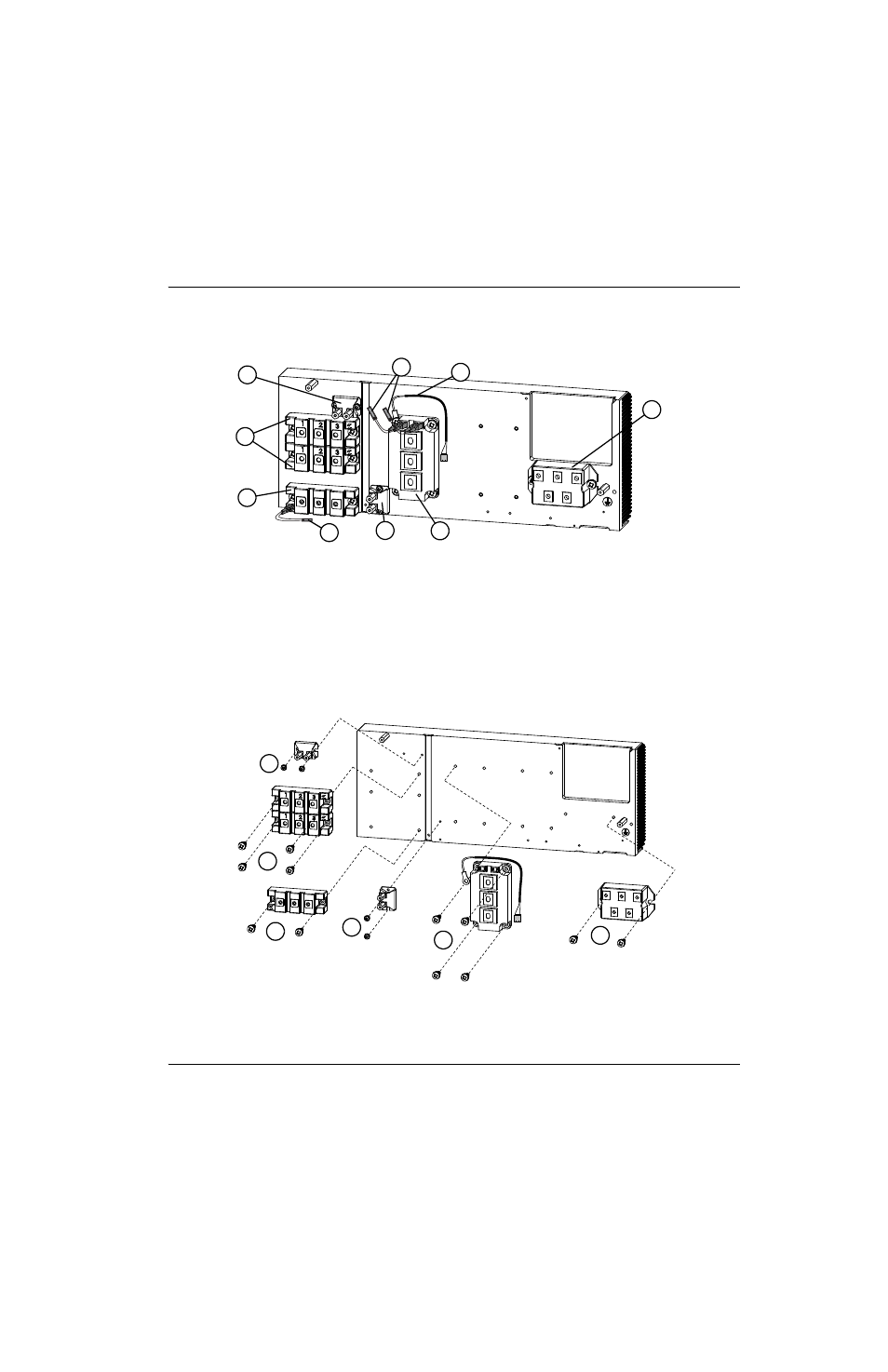
Figure 76 – Heatsink components
1
2
3
4
5
6
7
8
9
1
Snubber resistor 7.5 Ω 200 W (Kit 428137)
2
Output diode bridge (2) (Kit 428139)
3
Pilot arc IGBT (Kit 428138)
4
Pilot arc IGBT gate drive cable
5
Snubber resistor 15 Ω 200 W (Kit 228898)
6
Inverter IGBT module (Kit 428140)
7
Input diode bridge (Kit128746)
8
Thermal sensor (Kit 228805)
9
Inverter IGBT module gate drive cables
1
2
2
2
2
1
1
Torque to 17.3 kg-cm (15 inch-pounds).
2
Torque to 40 kg-cm (35 inch-pounds).
Advertising
This manual is related to the following products: