Replacing the torch quick disconnect receptacle, Remove the torch quick disconnect receptacle, 9 – power supply component replacement – Hypertherm Powermax125 Service Manua User Manual
Page 231: Figure 89
Powermax125 Service Manual 808070
231
9 – Power Supply Component Replacement
Replacing the torch quick disconnect receptacle
Remove the torch quick disconnect receptacle
1. Complete the following procedures:
a. See Disconnect the power and gas supply on page 166.
b. See Remove the power supply cover on page 172.
c. See Remove the component barrier on page 173.
d. See Remove the end panel bracket on page 174.
e. See Remove the fan shroud on page 216.
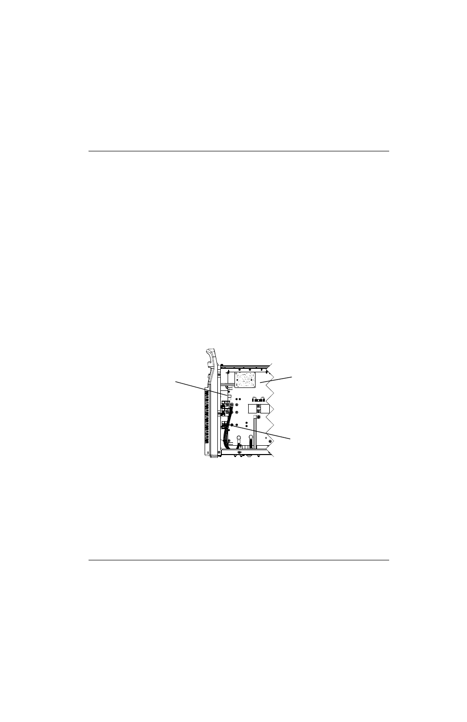
2. Unplug the wire connector from the J17 power board socket.
3. Disconnect the nozzle wires by removing the screw that secures the ring terminal to the power board.
Figure 89
4. From the fan side, pull the torch interface cable through the center grommet. See Figure 90 on page 232.
5. From the fan side, pull the nozzle wires through the protective sheathing that passes through the center panel.
6. Disconnect the 90° push-to-connect fitting by pushing in the plastic ring (closest to the brass nut) and pulling the
fitting away from the nut.
7. Disconnect the electrode wire and 2 output inductor wires by removing the brass nut that secures the ring terminal to
the quick disconnect receptacle.
The electrode wire and 2 output inductor wires are captured in the same wire connector.
Kit number
Description
Kit: Powermax125 quick disconnect receptacle replacement (power supply side)
J22
J27
WORK
LEAD
J26
_
RED
J18
ORG
J17
J32
J11
B
R
J28
RED
J17
Nozzle wire screw
Power board