Hypertherm Powermax125 Service Manua User Manual
Page 157
Powermax125 Service Manual 808070
157
8 – Troubleshooting and System Tests
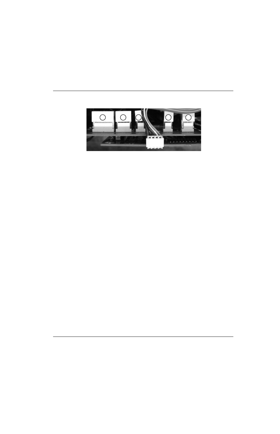
Figure 26
Remove the connector covers to access the pins on the top-rear of the power board.
If the +48 VDC value is incorrect:
Remove the fan connector (J1) and repeat the test.
If the value is now correct, replace the fan.
If the value is still incorrect, replace the power board.
If the +24 VDC value is incorrect:
Remove the pressure switch connector (J5) and repeat the test.
If the value is now correct, replace the pressure switch.
If the value is still incorrect, replace the pressure switch connector, remove the solenoid valve connector (J6) and
repeat the test. If the value is now correct, replace the solenoid valve. If the value is still incorrect, replace the power
board.
If the +5 VDC value is incorrect:
Remove the pressure sensor connector (J3) and repeat the test.
If the value is now correct, replace the pressure sensor.
If the value is still incorrect, remove the DSP board and repeat the test.
If the value is now correct, replace the DSP board.
If the value is still incorrect, replace the power board.
If the +3.3 VDC value is incorrect:
Remove the DSP board.
If the value is still incorrect, replace the power board.
Otherwise, the DSP board or control board may be bad. Do the following:
Reinstall the DSP board with the ribbon cable disconnected. If the value is now correct, replace the control
board. Otherwise, replace the DSP board.
1
2
3
4
5
1
Electronic regulator (J6)
2
Pressure switch/auxiliary contactor (J5)
3
Pressure sensor (J3)
4
Inverter temperature sensor (J2)
5
Fan (J1)