Hypertherm Powermax125 Service Manua User Manual
Page 123
Advertising
Powermax125 Service Manual 808070
123
8 – Troubleshooting and System Tests
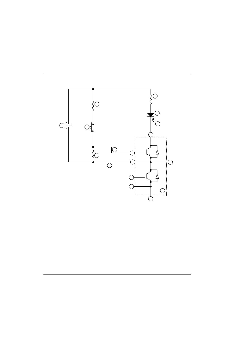
Figure 10 – Schematic for building an IGBT tester
3
4
5
6
7
8
9
11
12
13
14
15
16
2
10
17
1
1
IGBT module to be tested (inside the dashed line)
2
Collector (“C1” or “3”)
3
Emitter (“E2” or “2”)
4
Collector, Emitter (“C2E1” or “1”)
5
Gate (“G1” or “4”)
6
Emitter (“E1” or “5”)
7
Emitter (“E2” or “2”)
8
Gate (“G2” or “6”)
9
Red minigrabber test clip
10 D1 Red LED lamp (109092)
11 R3 2.0K (009036)
12 R4 2.0K (009036)
13 9 VDC battery
14 Normally open push-button switch
15 R1 3.01M (009464)
16 Black minigrabber test clip
17 Yellow minigrabber test clip
Advertising
This manual is related to the following products: