Hypertherm Powermax125 Service Manua User Manual
Page 208
Advertising
208
Powermax125 Service Manual 808070
9 – Power Supply Component Replacement
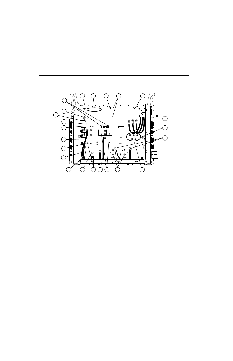
Figure 75 – 400 V CE / 380 V CCC power board
J6
J5
J3
J2
J1
RED
J18
ORG
J17
RED
J32
J11
B
R
J27
WORK
LEAD
J26
C152
C151
J25
+
_
+
_
J28
TP7
TP9
TP8
W
R
B
1
2
4
5
6
7
8
9
12
17
10
18
3
11
3
13
14
15
3
16
3
3
3
1
Gate drive connectors
2
J11
3
Board mounting screws (7)
4
J17
5
J18
6
Output inductor wires
7
Nozzle wires
8
Electrode wire
9
J32
10 Work lead
11 Transformer wires
12 4 μF capacitors
13 Capacitor screws (4)
14 PFC inductor wires
15 Input diode bridge screws (5)
16 AC input wires (3)
17 Transformer mounting screws
18 J6, J5, J3, J2, and J1
Advertising
This manual is related to the following products: