Or wires as shown in figure 127, Figure 127 – Hypertherm Powermax125 Service Manua User Manual
Page 273
Powermax125 Service Manual 808070
273
10 – Torch Component Replacement
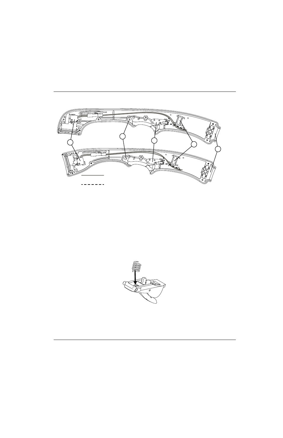
Figure 127
6. Press the torch body into the torch handle with the gas hose fitting’s flange aligned with the slot in the handle.
7. Align the strain relief with the strain relief slot in the handle. (See Figure 127 for the location of the strain relief slot.)
8. Compress the trigger spring into the front half of the trigger. Slide the trigger and spring into place.
Figure 128
9. Being careful that the handle and gas fitting flange do not pinch the wires, align the left half of the handle with the
right half. Verify that the trigger pivots are both located in the trigger pivot holes. (See
10. Install the handle screws loosely.
1
2
3
4
5
Cap-sensor switch wires
Start switch wires
1
Cap-sensor switch
2
Trigger’s pivot hole
3
Start switch
4
Slot for gas hose fitting’s flange
5
Slot for torch lead strain relief