9 – power supply component replacement, Figure 49 – Hypertherm Powermax125 Service Manua User Manual
Page 180

180
Powermax125 Service Manual 808070
9 – Power Supply Component Replacement
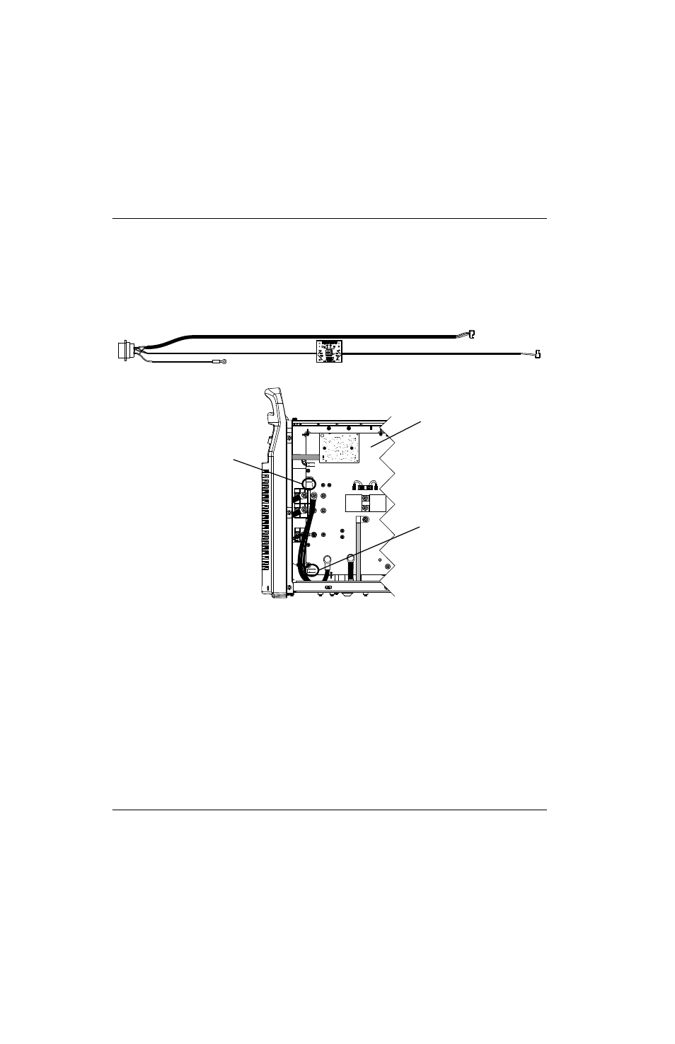
9. Route the larger diameter cable to J18. At J18 align the red wire in the cable connector with the “RED” that is printed
on the power board, and push the cable connector into the power board connector.
10. Route the smaller diameter cable to J32. At J32 align the red wire in the cable connector with the “RED” that is
printed on the power board, and push the cable connector into the power board connector.
Figure 49
11. From the fan side of the power supply, secure both cables in the cable clip attached to the center panel under the left
grommet.
12. Set the voltage divider board. (See Set the voltage divider board on page 181.)
13. Complete the following procedures:
a. See Install the component barrier on page 173.
b. See Install the power supply cover on page 172.
c. Reconnect the power and gas supply.
J22
J27
WORK
LEAD
J26
_
RED
J18
ORG
J17
J32
J11
B
R
J28
RED
J18
J32
Ground
J32
J18
Power board