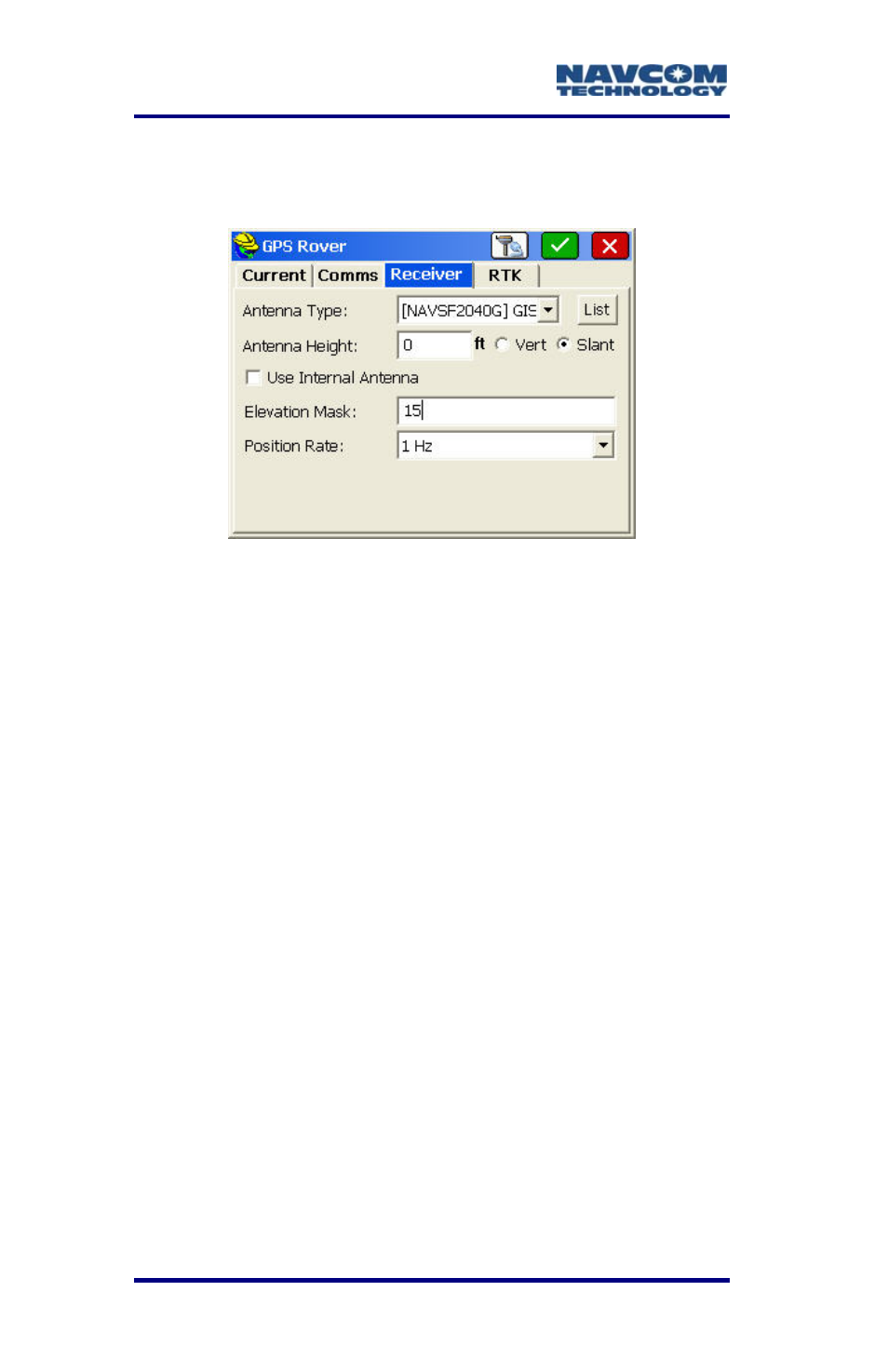
Figure 75: gps rover submenu – receiver tab . 110 – NavCom SF-2040 Rev.C User Manual
Page 114
LAND-PAK™ User Guide – Rev. C
5-110
Ref
7.
er to Figure 75 for the steps below:
Tap
the
Receiver tab.
Figure 75: GPS Rover Submenu – Receiver Tab
S
8.
t
•
If preferred, create a USER antenna
type so that the slant height
measurement can be taken at the
bottom outside edge of the battery
casing on the SF-2040 which is
coincidental with the Antenna
Reference point (ARP) per the NGS
Antenna Model. Refer to the GPS
Base Setup section above for
instructions on how to create a USER
ntenna.
If working in feet, the height can be
verified. Tap the Antenna Height field.
Enter the height in meters, for
e the options:
Antenna Type: [NAVCOMSF2040G]
a
•
current job units, and select Slant. Take the
slant height measurement at the center of the
black ring around the top of the receiver.
Antenna Height: Enter the height in the