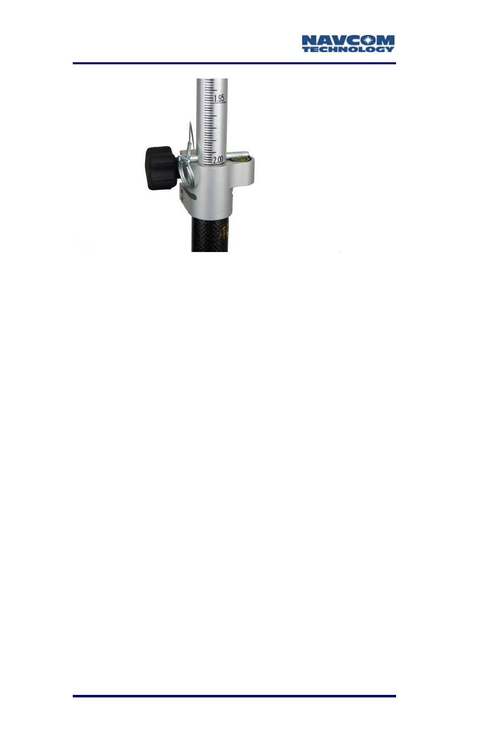
Figure 50: rover pole knob and locking pin – NavCom SF-2040 Rev.C User Manual
Page 92
Advertising

LAND-PAK™ User Guide – Rev. C
Figure 50: Rover Pole Knob and Locking Pin
Refer to Figure 50 for the steps below:
15. Tighten the rover pole knob to secure the pole
nsit case and
rover bag.
4-88
extension. If extended to 1.8 m, 2 m, or 2.2 m,
also insert the attached locking pin i
extension hole.
nto the
Extending the rover pole isolates the
sensor signals from the radio modem.
And reduces the possibility of satellite
signal bloc age by
k
passing
pedestrians or vehicles.
This concludes the rover test setup. Carefully,
16.
disassemble the rover attachments, and repack
all the equipment into the rover tra
Advertising
See also other documents in the category NavCom Equipment:
- SF-3050 Logging Data to Internal Memory SurvCE (4 pages)
- SF-3040 Logging Data to Internal Memory or SD Card (6 pages)
- SF-3050 Logging Data to USB Using SurvCE (4 pages)
- StarFire over IP (5 pages)
- SF-3050 Quick Start (4 pages)
- SF-3050 A Computationally Efficient Ambiguity Resolution (7 pages)
- StarFire (5 pages)
- StarFire to SW v3.0.12.0 (3 pages)
- SF-3050 Rev.I (196 pages)
- StarUtil-3000 Rev.G (177 pages)
- Sapphire Rev.L (450 pages)
- StarUtil-3000 Rev.A (119 pages)
- SF-3050 Rev.A (169 pages)
- SF-3050 Rev.B (201 pages)
- SF-3050 Rev.D (235 pages)
- Rinex Utility Rev.D (17 pages)
- SF-3040 Quick Start (4 pages)
- SF-3040 Rev.F (217 pages)
- SurveCE Integration Rev.A (150 pages)
- Install Utility Rev.C (26 pages)
- LAND-PAK Quick Start Rev.B (7 pages)
- LAND-PAK Rev.E (156 pages)
- StarUtil Rev.C (58 pages)
- LAND-PAK Rev.N (194 pages)
- StarUtil Rev.B (8 pages)
- StarUtil Rev.F (134 pages)
- SF-2040 Rev.E (63 pages)
- RT-3010 Rev.E (61 pages)
- StarFire Satellite Change Rev.G (24 pages)
- StarFire Satellite Change Rev.I (23 pages)
- TS Collecting Receiver (2 pages)
- TS Factory Default (2 pages)
- LAND-PAK Rev.F (159 pages)
- SF-2040 Rev.F (93 pages)
- RT-3020 Rev.F (93 pages)
- SF-2110 Quick Start Rev.A (2 pages)
- StarPac Rev.A (15 pages)
- StarControl Rev.C (56 pages)
- SF-2050 Rev.F (99 pages)
- TruBlu Rev.A (2 pages)
- VueStar Rev.B (13 pages)
- SF-2110 Rev.B (99 pages)
- StarUtil-2110 Rev.A (85 pages)
- RT-3010 Rev.F (89 pages)