Figure 48: mounting radio modem – NavCom SF-2040 Rev.C User Manual
Page 90
LAND-PAK™ User Guide – Rev. C
4-86
radio modem and Carlson Explo
bipod legs by shifting the offset
rer bise
weight t
same side as the bipod legs. Tighten th
ct the
o the
e
.
Th
tra
8. Mo
la
600
knob. Do not over tighten
e following steps use equipment from the rover
nsit case:
unt the Carlson Explorer 600+ to the crad
mp below the LCD display. Verify the Explore
le
r
c
+ is secure.
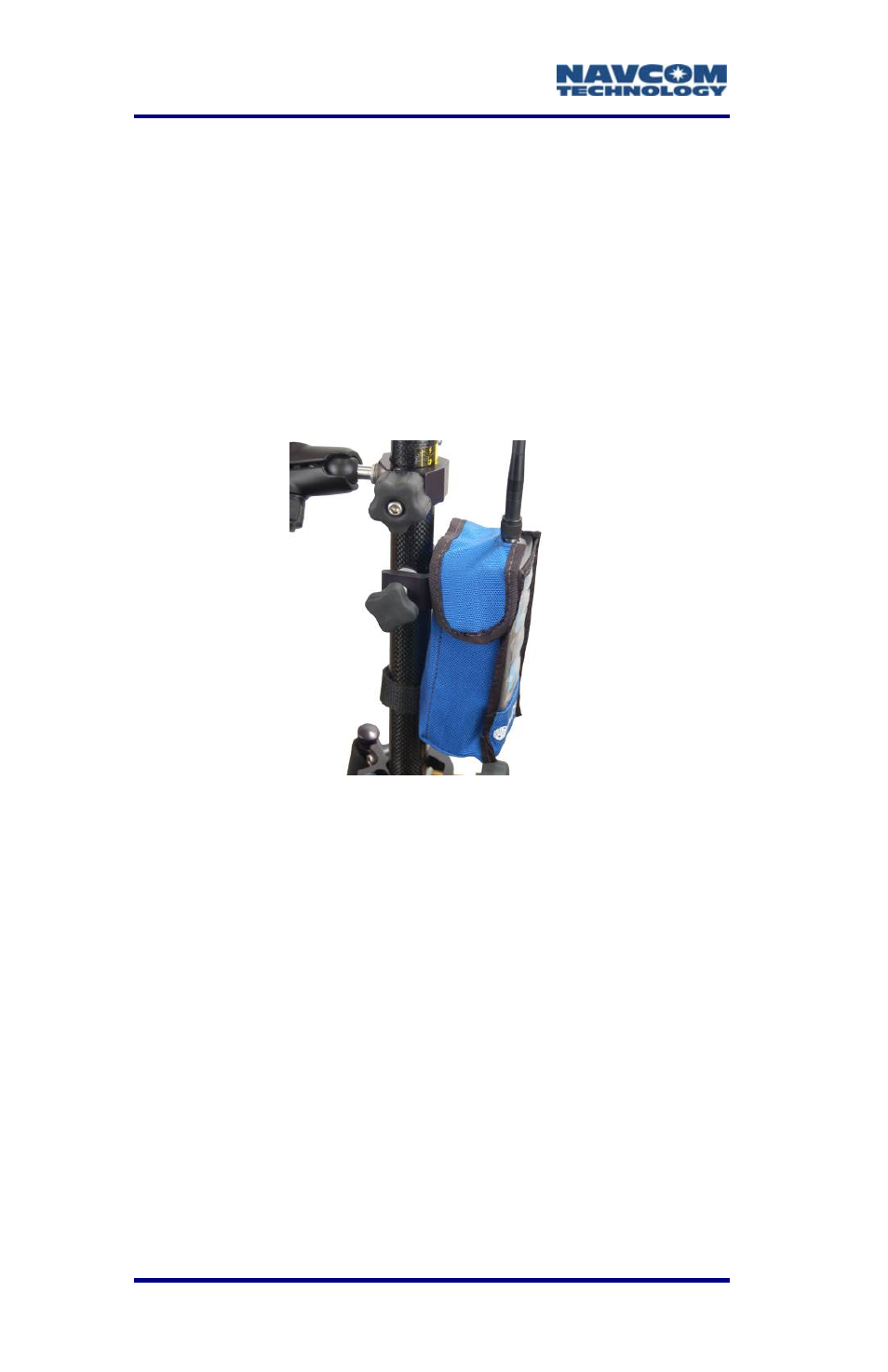
Figure 48: Mounting Radio Modem
Refer to Figure 48 for the steps below:
9. Screw the radio modem antenna to the female
TNC connector on the top of the 3ASd radio
modem.
10.
t
t
11. s
SF
Bat
Using the strap and the clamp on the radio bag,
mount the 3ASd radio modem to the rover pole
below the Carlson Explorer 600+ cradle. The
rover setup is more stable if the radio modem
bisects the bipod legs by shifting the offset weigh
to he same side as the bipod legs.
In ert the two lithium-ion battery packs into the
-2040 GIS PM Sensor. Refer to Chapter 3
tery Charging for details.