Figure 49: navcom rover cable connections – NavCom SF-2040 Rev.C User Manual
Page 91
Advertising
LAND-PAK™ User Guide – Rev. C
4-87
12. Scr
sec
dis
ew the sensor onto the rover pole. When
uring the sensor, make sure that the front
play faces the radio modem for easy access.
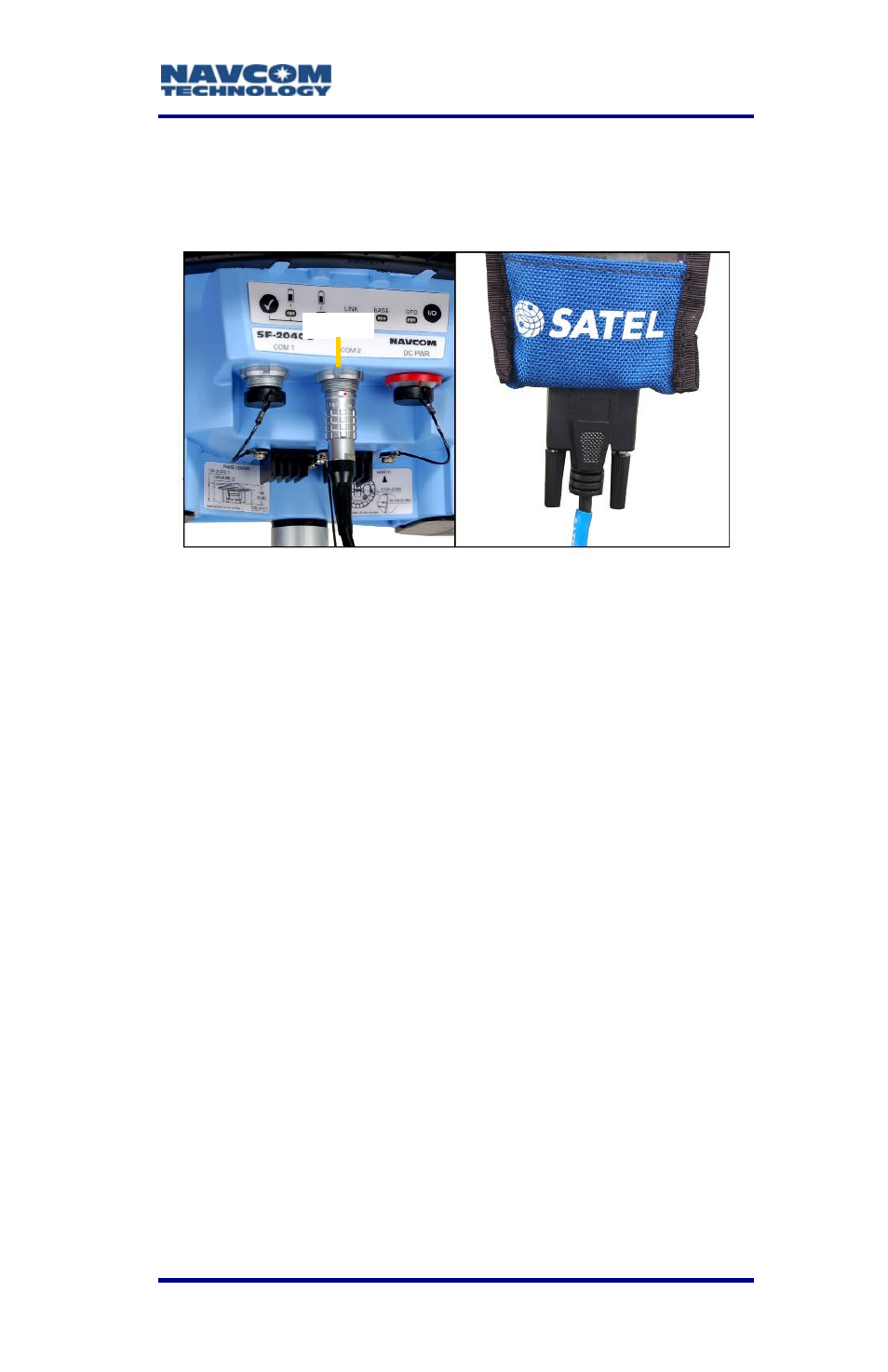
Figure 49: NavCom Rover Cable Connections
Refer to Figure 49 for the steps below:
13. Connect the NavCom rover radio modem cable:
• Connect the serial 9-Pin end of the cable to
the female serial connector on the bottom of
the radio modem.
• C
e
onnect the LEMO 7-Pin end of the cable to
Sensor.
14. Extend the aluminum extension of the rover pol
to the maximum height possible.
COM 2 of the SF-2040 GIS PM
COM2
Advertising
See also other documents in the category NavCom Equipment:
- SF-3050 Logging Data to Internal Memory SurvCE (4 pages)
- SF-3040 Logging Data to Internal Memory or SD Card (6 pages)
- SF-3050 Logging Data to USB Using SurvCE (4 pages)
- StarFire over IP (5 pages)
- SF-3050 Quick Start (4 pages)
- SF-3050 A Computationally Efficient Ambiguity Resolution (7 pages)
- StarFire (5 pages)
- StarFire to SW v3.0.12.0 (3 pages)
- SF-3050 Rev.I (196 pages)
- StarUtil-3000 Rev.G (177 pages)
- Sapphire Rev.L (450 pages)
- StarUtil-3000 Rev.A (119 pages)
- SF-3050 Rev.A (169 pages)
- SF-3050 Rev.B (201 pages)
- SF-3050 Rev.D (235 pages)
- Rinex Utility Rev.D (17 pages)
- SF-3040 Quick Start (4 pages)
- SF-3040 Rev.F (217 pages)
- SurveCE Integration Rev.A (150 pages)
- Install Utility Rev.C (26 pages)
- LAND-PAK Quick Start Rev.B (7 pages)
- LAND-PAK Rev.E (156 pages)
- StarUtil Rev.C (58 pages)
- LAND-PAK Rev.N (194 pages)
- StarUtil Rev.B (8 pages)
- StarUtil Rev.F (134 pages)
- SF-2040 Rev.E (63 pages)
- RT-3010 Rev.E (61 pages)
- StarFire Satellite Change Rev.G (24 pages)
- StarFire Satellite Change Rev.I (23 pages)
- TS Collecting Receiver (2 pages)
- TS Factory Default (2 pages)
- LAND-PAK Rev.F (159 pages)
- SF-2040 Rev.F (93 pages)
- RT-3020 Rev.F (93 pages)
- SF-2110 Quick Start Rev.A (2 pages)
- StarPac Rev.A (15 pages)
- StarControl Rev.C (56 pages)
- SF-2050 Rev.F (99 pages)
- TruBlu Rev.A (2 pages)
- VueStar Rev.B (13 pages)
- SF-2110 Rev.B (99 pages)
- StarUtil-2110 Rev.A (85 pages)
- RT-3010 Rev.F (89 pages)