Logic connections, Figure 61 – Basler Electric BE1-11t User Manual
Page 106
94
9424200995 Rev H
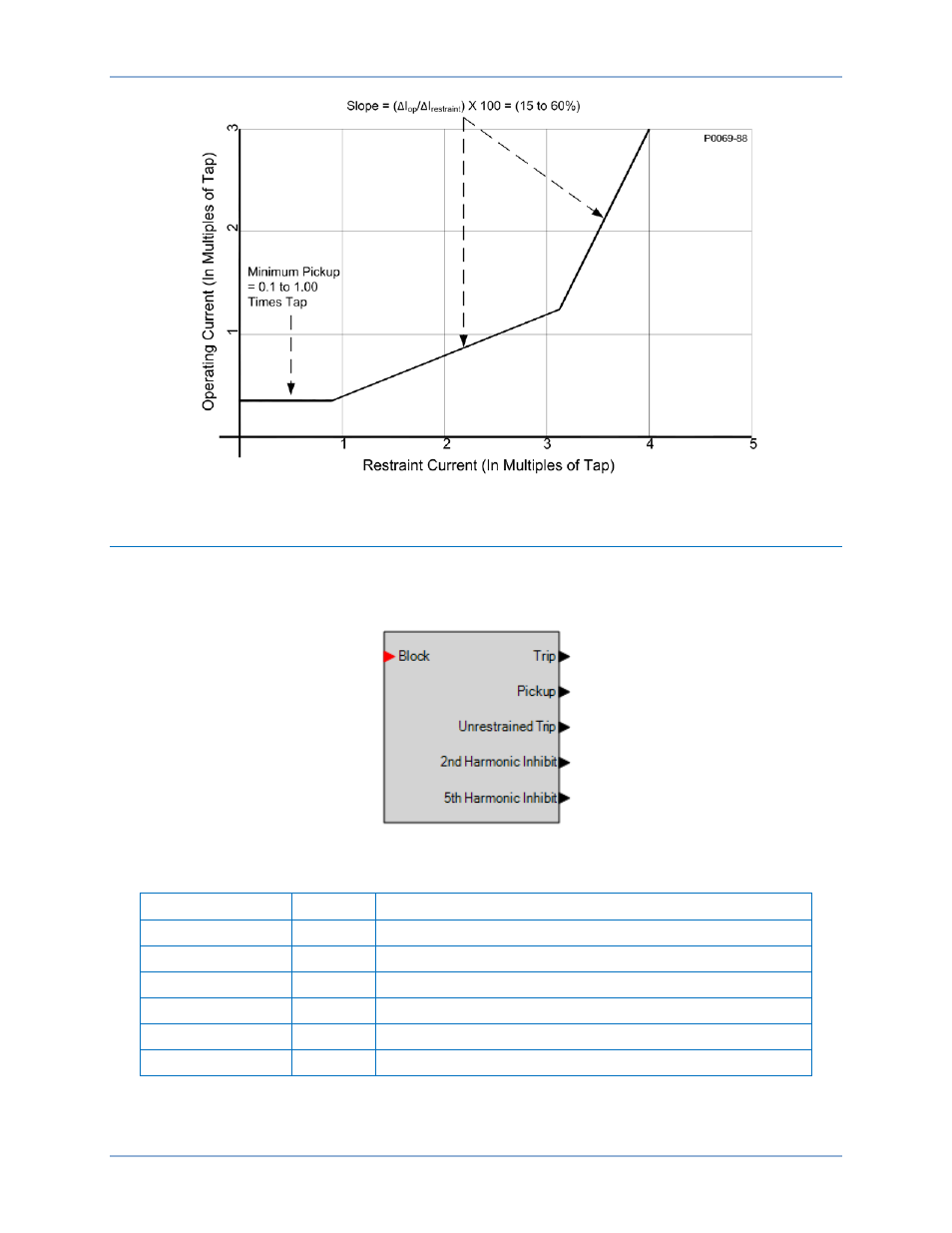
Figure 61. Percentage Restrained Differential Characteristic
Logic Connections
Phase current differential element logic connections are made on the BESTlogicPlus screen in
BESTCOMSPlus. The phase current differential element logic block is illustrated in Figure 62. Logic
inputs and outputs are summarized in Table 33.
Figure 62. Phase Current Differential Element Logic Block
Table 33. Logic Inputs and Outputs
Name
Function
Purpose
Block
Input
Disables the 87 function when true
Trip
Output
True when the 87 element is in a trip condition
Pickup
Output
True when the 87 element is in a pickup condition
Unrestrained Trip
Output
True when the 87 element is in an unrestrained trip condition
2
nd
Harmonic Inhibit
Output
True when the 87 is inhibited by 2
nd
harmonic ratio
5
th
Harmonic Inhibit
Output
True when the 87 is inhibited by 5
th
harmonic ratio
0BPhase Current Differential (87) Protection
BE1-11t