Connection settings for current differential, Figure 231), N table 94 – Basler Electric BE1-11t User Manual
Page 300
288
9424200995 Rev H
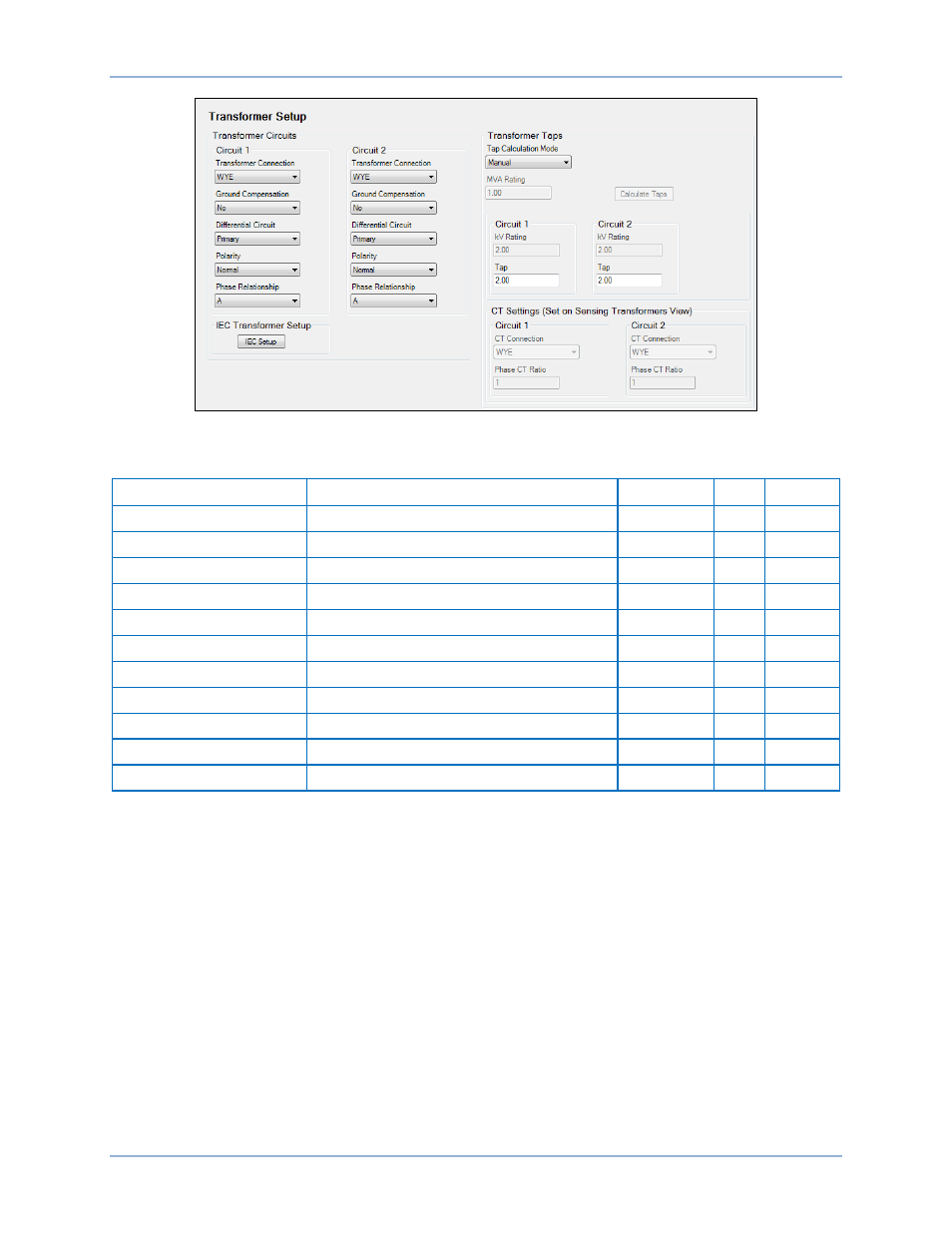
Figure 231. Transformer Setup Screen
Table 94. Transformer Settings
Setting
Range
Increment
Unit
Default
Tap Calculation Mode
Manual or Automatic
n/a
n/a
Manual
MVA Rating
0.5 to 10,000
0.1
n/a
0.5
kV Rating
0.01 to 1,000
n/a
n/a
n/a
Tap
2 to 20 (5A CTs) or 0.4 to 4 (1A CTs)
0.01
n/a
2.00
CT Connection
Set on the Sensing Transformers screen
n/a
n/a
n/a
Phase CT Ratio
Set on the Sensing Transformers screen
n/a
n/a
n/a
Transformer Connection
WYE, DAB, DAC, ZAB, ZAC, or NA
n/a
n/a
WYE
Ground Connection
Yes or No
n/a
n/a
No
Differential Circuit
Primary, Secondary, or None
n/a
n/a
Primary
Polarity
Yes or No
n/a
n/a
No
Phase Relationship
A, B, or C
n/a
n/a
A
Connection Settings for Current Differential
When the zone of protection includes a transformer, it may be necessary to provide phase angle and zero
sequence compensation to the currents used by the Phase Current Differential Protection (87) element.
See Figure 232 and Figure 233. For each input circuit, a setting is provided to enter the transformer
connections associated with that input.
Configuration
BE1-11t