Figure 64), N table 35 – Basler Electric BE1-11t User Manual
Page 109
9424200995 Rev H
97
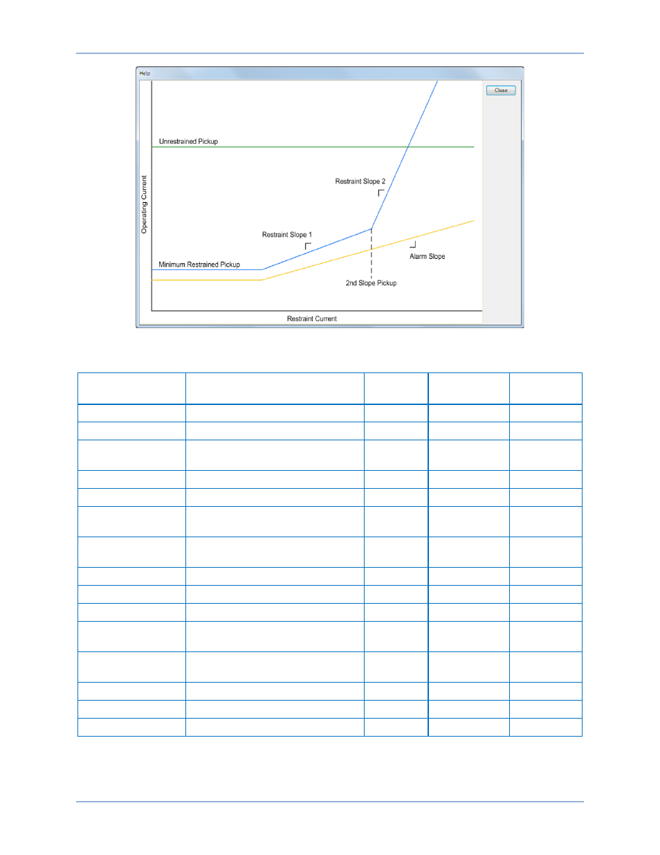
Figure 64. Phase Current Differential Operation Chart
Table 35. Operational Settings
Setting
Range
Increment
Unit of
Measure
Default
87 Mode
Disabled or Percent Differential
n/a
n/a
Disabled
Slope Mode
Maximum or Average
n/a
n/a
Maximum
Minimum
Restrained Pickup
0 or 0.1 to 1
0.01
n/a
0
Restraint Slope 1
5 to 100
1
percent
45
Time Delay
0 to 60,000
varies
milliseconds
0
CT Circuit 1 Tap
Set on the System Parameters,
Transformers Setup screen
n/a
n/a
n/a
CT Circuit 2 Tap
Set on the System Parameters,
Transformers Setup screen
n/a
n/a
n/a
2
nd
Slope Pickup
0 or 0.1 to 20
0.01
n/a
0
Restraint Slope 2
15 to 140
1
percent
45
Slope Alarm
0 or 50 to 100
1
percent
0
Unrestrained
Tripping Mode
Enabled or Disabled
n/a
n/a
Disabled
Unrestrained
Tripping Pickup
0 to 21
1
n/a
0
Harmonics Mode
Independent or Shared
n/a
n/a
Independent
2
nd
Harmonic
0 or 5 to 75
1
percent
0
5
th
Harmonic
0 or 5 to 75
1
percent
0
BE1-11t
0BPhase Current Differential (87) Protection