Element blocking, X block initiate, Timer – Basler Electric BE1-11t User Manual
Page 129: Block initiate 62-x
9424200995 Rev H
117
time delay for the output to change to false if it is presently true and the initiate input becomes false and
stays false.
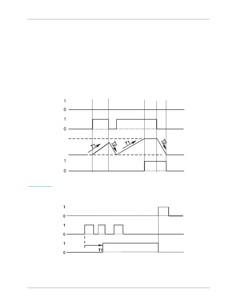
In the example shown in Figure 79, T2 is set to half of the T1 setting. The initiate input becomes true and
the timer starts integrating toward pickup. Prior to timing out, the Initiate input toggles to false and the
timer starts resetting at twice the rate as it was integrating toward time out. It stays false long enough for
the integrating timer to reset completely but then toggles back to true and stays true for the entire duration
of time T1. At that point, the timer’s output is toggled to true. Then later, the initiate Input becomes false
and stays false for the duration of T2. At that point, the output of the timer is toggled to false.
This type of timer is useful in applications where a monitored signal might be hovering at its threshold
between on and off. For example, it is desired to take some action when current is above a certain level
for a certain period. An instantaneous overcurrent (50) element could be used to monitor the current level.
Thus, if the current level is near the threshold so that the Initiate input toggles between true and false
from time to time, the function will still time out as long as the time that it is true is longer than the time
that it is false. With a simple pickup/dropout timer, the timing function would reset to zero and start over
each time the Initiate input became false.
Figure 79. Integrating Timer Mode
Latched Mode
A one shot timer starts its timing sequence when the Initiate input changes from false to true. The timer
will operate for Delay Time (T1) and then the output will latch true. Additional Initiate input changes of
state are ignored. Time (T2) is ignored. Refer to Figure 80.
Figure 80. Latched Mode
Element Blocking
The Block input provides logic-supervision control of the element. When true, the Block input disables the
element by forcing the element output to logic 0 and resetting the element timer. Connect the element
P
0
0
3
5
-3
4
0
2
-2
7
-0
6
62-x
Block
Initiate
100%
0%
Timer
P
0
0
3
5
-3
5
0
2
-2
7
-0
6
Block
Initiate
62-x
BE1-11t
Logic Timers (62)