Offline logic simulator, Bestlogic™plus file management, Figure 197 – Basler Electric BE1-11t User Manual
Page 265: Bestlogic ™plus file management
9424200995 Rev H
253
Figure 197. Pickup and Dropout Timer Logic Blocks
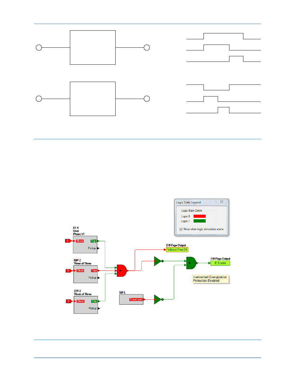
Offline Logic Simulator
The offline logic simulator allows you to change the state of various logic elements to illustrate how that
state travels through the system. Before running the logic simulator, you must click the Save button on the
BESTlogicPlus toolbar to save the logic to memory. Changes to the logic (other than changing the state)
are disabled when the simulator is enabled. Colors are selected by clicking the Options button on the
BESTlogicPlus toolbar. By default, Logic 0 is red and Logic 1 is green. Using your mouse, double-click on
a logic element to change its state.
An example of the offline logic simulator is shown in Figure 198. Output 1 is Logic 0 (red) when Input 1 is
Logic 0 (red) and Fixed 1 is Logic 1 (green).
Figure 198. Offline Logic Simulator Example
BESTlogic
™Plus File Management
To manage BESTlogicPlus files, use the Settings Explorer to open the BESTlogicPlus Programmable
Logic tree branch. The BESTlogicPlus Programmable Logic toolbar is used to manage BESTlogicPlus
Initiate
Pickup Time
Output
Initiate
Dropout Time
Output
Pickup
Timer
Dropout
Timer
Output
Output
Initiate
Initiate
P0048-03
BE1-11t
BESTlogic
™Plus