Maximum torque angle and directional tests – Basler Electric BE1-11t User Manual
Page 99
9424200995 Rev H
87
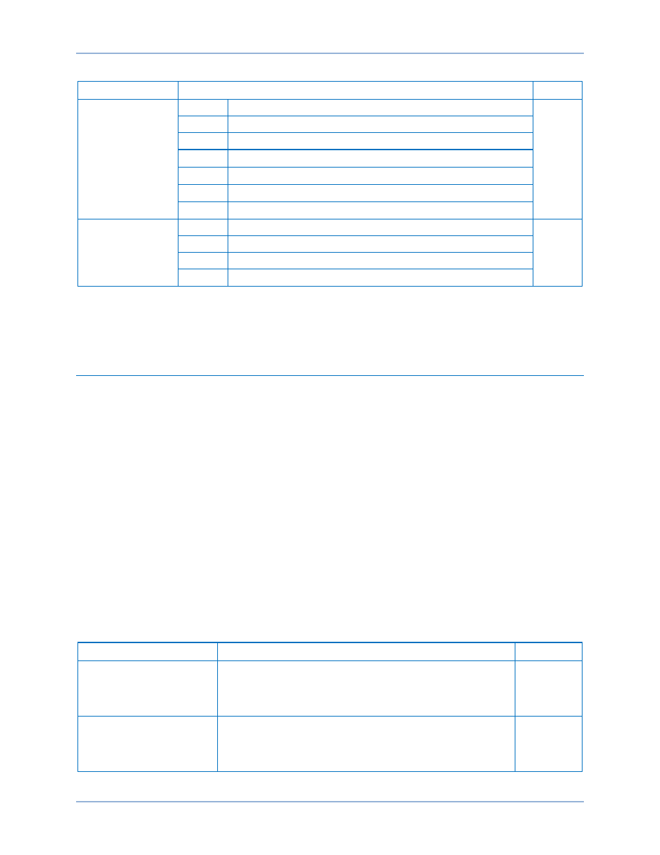
Table 31. Polarization Settings
Setting
Range/Purpose
Default
67N Polarization
Method
IG
Use Zero Sequence Current Polarization
IG/Q/V
Q
Use Negative Sequence Polarization
V
Use Zero Sequence Polarization
IG/Q/V
* Use all three polarization methods
IG/Q
*
Use IG and Q polarization methods
IG/V
*
Use IG and V polarization methods
Q/V
*
Use Q and V polarization methods
Zero-Sequence
Mode
VOIN
Calculated Zero Sequence Volt, Calculated Zero Sequence Current
VOIN
VOIG
Calculated Zero Sequence Volt, Measured Ground Current
VXIN
Measured 3V0-VX, Calculated Zero Sequence Current
VXIG
Measured 3V0-VX, Measured Ground Current
* Modes IG/Q/V, IG/Q, IG/V, and Q/V are logical ORs of Modes IG, Q, and V and are used to set up dual
or possibly triple polarization techniques for the neutral elements. Thus, if more than one directional
supervision element is enabled, any element can enable tripping if the appropriate forward or reverse
directional decision is made.
Maximum Torque Angle and Directional Tests
The directional algorithm requires a user settable maximum torque angle (MTA). There is an MTA setting
for positive-sequence calculations, an MTA setting for negative-sequence calculations, and an MTA
setting for zero-sequence calculations. These settings are separate from the power line impedance
parameters (Z
1
and Z
0
used for distance to fault calculations) because some applications require a
polarizing MTA different from the "distance to fault" line impedance angle.
Each MTA can be set over the range of 0 to 90 degrees (I lag E) in 1 degree steps. These parameters are
input into the BE1-11t using BESTCOMSPlus. Open the System Parameters, Power System tree branch.
A fault current is considered to be in a forward direction when the sequence current, after being offset by
the line angle, is in phase with the same sequence voltage. The forward direction zone extends for
approximately
±90° from the nominal line angle. A similar argument applies for the reverse direction with
the current 180
° out of phase from the voltage. The angle of Z1 is used during positive-sequence
directional test and the angle of Z2 is used during negative-sequence directional test. Likewise, the angle
of Z0 is used during the zero-sequence directional test. Angle compensation is not required for current
polarization since the polarizing quantity IG is inherently compensated.
Note that (not forward) does not necessarily imply reverse. Sufficient current and voltage must be present
to declare direction. Internally, the BE1-11t also uses several constant limits to determine if the system
levels are adequate to perform reliable directional tests and set directional bits. See Table 32.
Table 32. Internal Constants
Internal Constant
Purpose
Value
Positive-Sequence
Current
Minimum I1 current threshold for Positive-Sequence test
0.50 A for
5A CTs
and 0.1 A
for 1A CTs
Zero-Sequence Current
Minimum 3I0 current threshold for Current Polarization test
0.25 A for
5A CTs
and 0.05 A
for 1A CTs
BE1-11t
Directional Overcurrent (67) Protection