Breaker control switch (101), Element operation, Control of breaker control switch – Basler Electric BE1-11t User Manual
Page 135
9424200995 Rev H
123
Breaker Control Switch (101)
The breaker control switch (101) element provides manual control of a circuit breaker or switch without
using physical switches or interposing relays. Both local and remote control is possible. A virtual switch
can be used instead of a physical switch to reduce costs with the added benefit that the virtual switch can
be operated both locally from the front panel and remotely from a substation computer or Ethernet
connection to an operator’s console.
Element logic connections are made on the BESTlogic
™Plus screen in BESTCOMSPlus® and element
operational settings are configured on the Breaker Control Switch settings screen in BESTCOMSPlus. A
summary of the logic inputs and outputs and operational settings appears at the end of this chapter.
BESTCOMSPlus Settings Navigation Path: Settings Explorer, Control, Breaker Control Switch (101)
HMI Settings Navigation Path: Settings Explorer, Control, Breaker Switch 101
BESTCOMSPlus Control Navigation Path: Metering Explorer, Control, Breaker Control Switch
HMI Control Navigation Path: Metering Explorer, Control, 101 Breaker Control SW
Element Operation
The breaker control switch emulates a typical breaker control switch with a momentary close, spring
return, trip contact output (Trip), a momentary close, spring return, close contact output (Close), a trip slip
contact output (TSC), and a close slip contact output (CSC). The trip slip contact output retains the status
of the last trip control action. That is, it is true (closed) in the after-trip state and false (open) in the after-
close state. The close slip contact output retains the status of the last close control action. It is false
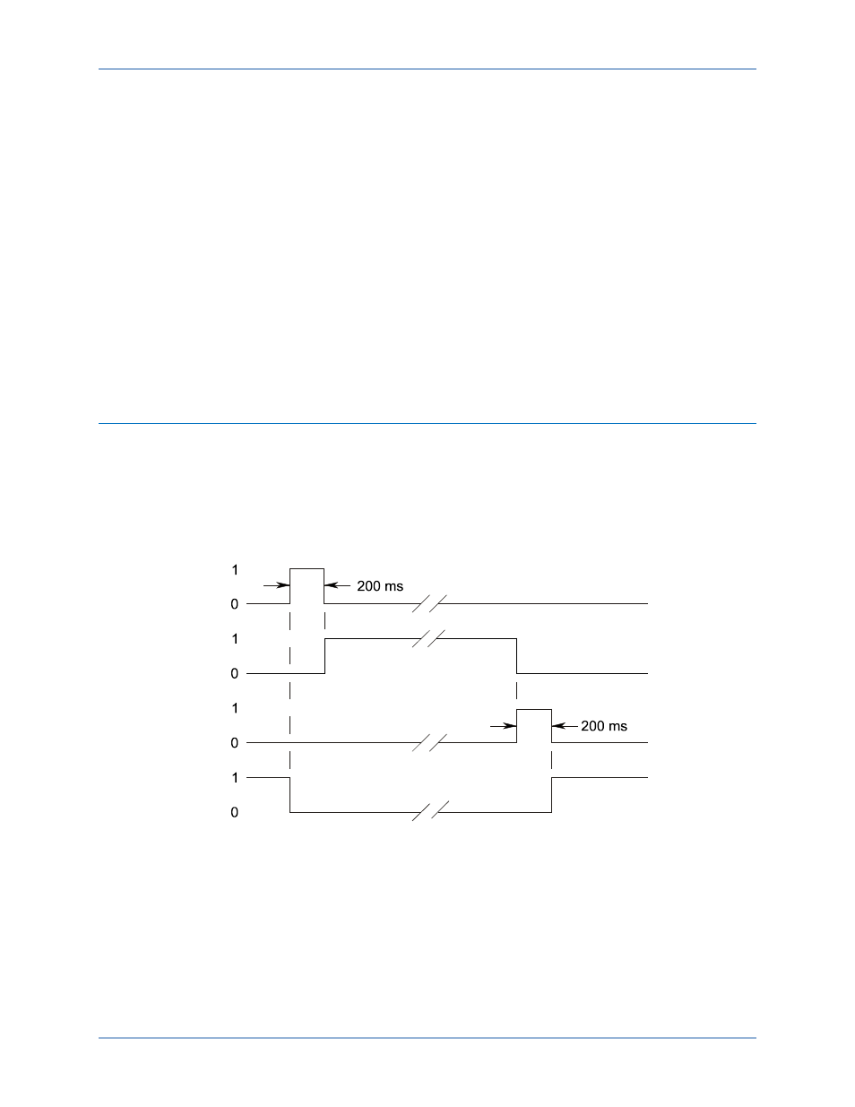
(open) in the after-trip state and true (closed) in the after-close state. Figure 86 shows the state of the
TSC and CSC logic outputs with respect to the state of the Trip and Close outputs.
Figure 86. Breaker Control Switch State Diagram
When the breaker control switch is controlled to trip, the Trip output pulses true (closed) for approximately
200 milliseconds and the TSC output goes true (closed). When the breaker control switch is controlled to
close, the CSC output pulses true (closed) and the TSC goes false (open). The status of the slip contact
outputs is saved to nonvolatile memory so that the BE1-11t will power up with the contact in the same
state as when the BE1-11t was powered down.
Control of Breaker Control Switch
The state of virtual control switches can be controlled using the front-panel interface or through
BESTCOMSPlus when the connection state is active. Using select-before-operate, perform the following
steps to control the switch using BESTCOMSPlus:
Trip
TSC
Close
CSC
P
0
0
3
5
-3
9
0
2
-2
4
-0
6
BE1-11t
Breaker Control Switch (101)