Pickup verification (v1 mode) – Basler Electric BE1-11t User Manual
Page 357
9424200995 Rev H
345
Step 2: Prepare to monitor the 59X-1 timings. Timing accuracy is verified by measuring the elapsed
time between a sensing voltage change and OUT1 closing.
Step 3: Connect and apply a 150 Vac, three-phase voltage source to terminals C13 (A-phase), C14 (B-
phase), C15 (C-phase), and C16 (neutral).
Step 4: Step the A-phase voltage up to 215 volts. Measure the time delay and record the result.
Step 5: Repeat step 4 for the 5,000 ms and 10,000 ms time delay settings of Table 135. Record the
results.
Step 6: (Optional.) Repeat steps 1 through 5 for settings group 1, 2, and 3.
Step 7: (Optional.) Repeat steps 1 through 6 for 59X-2, 59X-3, and 59X-4.
Pickup Verification (V1 Mode)
Step 1: Use BESTCOMSPlus to send the operational settings in Table 136 to the BE1-11t. Reset all
targets.
Table 136. Operational Settings (V1 Mode)
Setting
Value
BESTCOMSPlus Screen
Description
Phase VT Ratio
1
System Parameters, Sensing
Transformers
Sets phase VT ratio to 1
Phase VT
Connection
4W-Y
System Parameters, Sensing
Transformers
Sets phase VT connection to
4W-Y
27/59 Mode
PN
System Parameters, Sensing
Transformers
Sets 27/59 mode to phase-
neutral
Element Mode
V1
Protection, Voltage, Overvoltage
(59X-1)
Enables 59X-1 function for V1
mode
Timing Mode
Definite
Protection, Voltage, Overvoltage
(59X-1)
Selects definite timings
59X-1 V1
Enabled Target Configuration, Targets
Enables V1 target for 59X-1
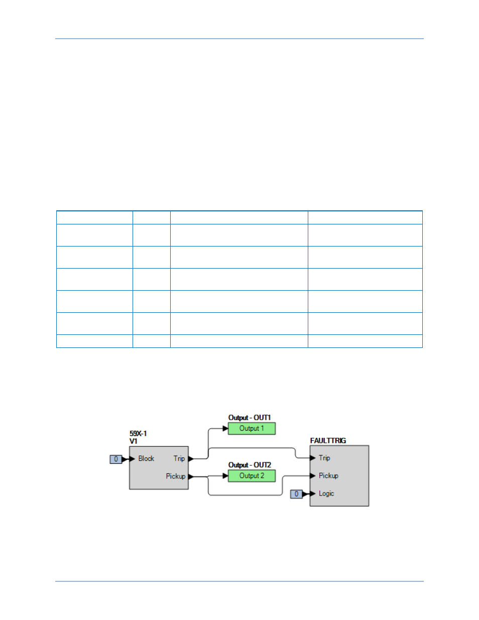
Step 2: Use BESTCOMSPlus to configure the BESTlogicPlus programmable logic shown in Figure 246.
•
Blocking is disabled.
•
OUT1 closes for 59X-1 Trip.
•
OUT2 closes for 59X-1 Pickup.
•
Fault recording is enabled.
Figure 246. BESTlogicPlus Settings (V1 Mode)
Step 3: Use BESTCOMSPlus to open the Protection, Voltage, Overvoltage (59X-1) screen and send
the first row of test settings in Table 137 to the BE1-11t.
BE1-11t
Auxiliary Overvoltage (59X) Test