Voltage corresponding to parameter pm 1412, Voltage corresponding to parameter pm 1413 – Yaskawa PC NC User Manual
Page 187
4 - 25
YASNAC PCNC Operating Manual
Chapter 4: Maintenance
(d) Start interlock signal is input.
If I/O monitor #3004 D2 = 1, start interlock is ON.
Normal: #3004 D2 = 0
(e) Axis interlock is input.
Check I/O monitor #3087 D0 to D4.
Normal: #3078 D0 to D4 = 1
(f) Setting of the servo system is incorrect.
Check whether the axes can be moved manually.
(8) Spindle Rotation is Impossible
(a) Error in a program (no S command or no spindle start M code)
Check the contents of the program on the [RUN] screen.
(b) Start signal has not been input.
Check the output signals (#1100s) on the I/O monitor screen.
(c) Spindle rotation command has not been output.
Check #3654 to #3656 on the 110 monitor screen.
(d) The spindle drive is in the alarm status.
Check the alarm indication of the spindle drive.
(e) Combination of GRO and SOR is incorrect, or “0’ is input for parameter pm1412
or pm1413.
Check I/O monitor #3110 by referring to Table 4.21.
Note: If” 1” is set for parameter pm1000 D5, SSTP input is reversed.
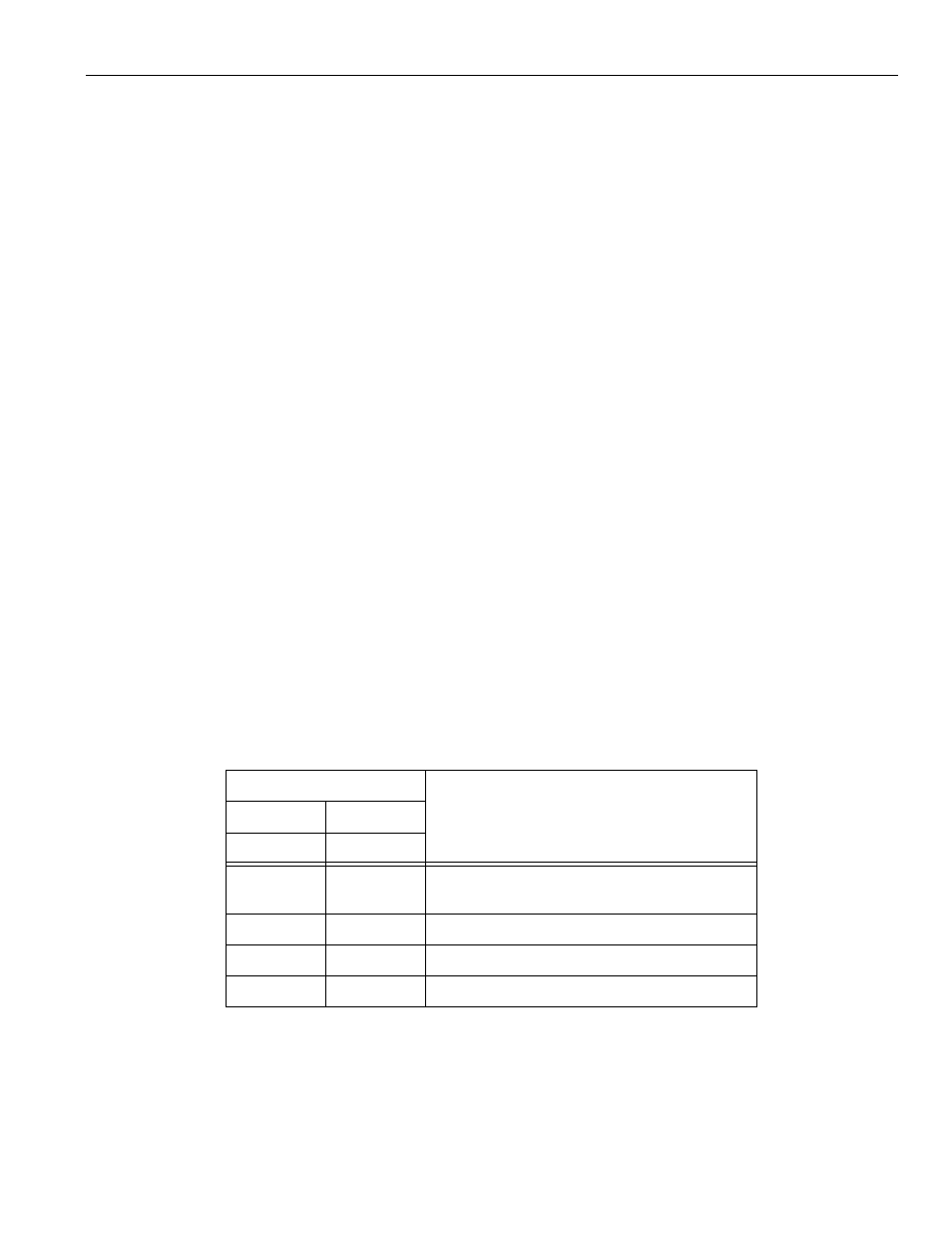
Table 4.1.7.2: Input of GRO and SOR andS4-digit Command Analog Voltage
I/O Monitor #3110
S4-digit Command Analog Voltage
D7
D6
GRO Input
SOR Input
0
0
Voltage corresponding to the spindle speed
specified in the NC program.
0
1
Voltage corresponding to parameter pm 1412
1
0
Voltage corresponding to parameter pm 1413
1
1
0V