A3 - 111 – Yaskawa PC NC User Manual
Page 351
A3 - 111
YASNAC PCNC Operating Manual
APPENDIX 3: Parameter Tables
NC System
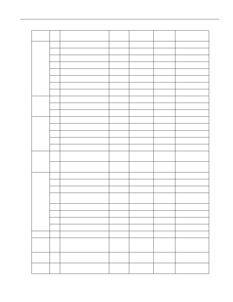
Address
Bit
Description
Register
Units
Minimum
Value
Maximum
Value
Long Description
0
0
Single-block switch
0
1
1
Machine lock switch
0
1
2
Dry run switch
0
1
3
Block delete switch
0
1
4
Manual absolute switch
0
1
5
Auxiliary function lock switch
0
1
6
Display lock switch
0
1
7
Edit Lock switch
0
1
1
0
Optional stop switch
0
1
1
Start lock switch
0
1
2
Z-axis neglect switch
0
1
2
0
Mirror image 1
0
1
1
Mirror image 2
0
1
2
Mirror image 3
0
1
3
Mirror image 4
0
1
4
Mirror image 5
0
1
3
1
Axis disconnection designation
(4th-axis)
0
1
2
Axis disconnection designation
(5th-axis)
0
1
5
0
Manual zero return switch
0
1
1
No. 2 manual zero return switch
0
1
2
Interruption point return switch
0
1
3
Automatic mode handle offset
switch
0
1
4
Setup point return switch
0
1
5
Playback switch
0
1
6
F1-digit switch
0
1
7
Program restart switch
0
1
7
6
“0” data in parameter output
0
1
48
0
Servo current adjustment
0
1
Servo U-phase V-phase
current command offset
adjustment
107
Manual skip measuring point
monitor
0
6
109
Internal system number switch
setting
0
1