Yaskawa PC NC User Manual
Page 41
2 - 18
YASNAC PCNC Operating Manual Chapter 2: Basic Operation of YASNAC PCNC
the reference point return direction manually only if the reference point return switch
is turned OFF.
3. If commands have been read to the buffer area during automatic operation, manual
reference point return must not be executed. If manual return operation is executed,
the data in the buffer area is cleared.
1. Immediately after the power is turned ON, the axis start manual or automatic reference
point return operation independent of the present axis position. However, reference point
return cannot be executed correctly if the axis is located in area B. In this case, the axis
must be returned to area A before executing reference point return.
2. If the MODE SELECT switch setting is changed while an axis is moving automatically to
the reference point, an alarm (alarm 2141 to 2145 reference point return interruption error)
occurs.
3. Reference point return cannot be executed when the MACHINE LOCK switch is ON.
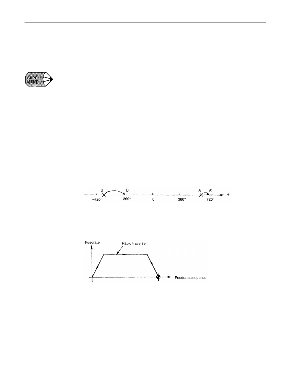
4. With a rotary axis, it is possible to execute automatic reference point return as with a
linear axis.With a rotary axis, if it has been moved by more than ± 360.000° from the
reference point established first, reference point return is executed to the closest reference
point in the preset direction of reference point return.
The illustration below shows how the reference point return is executed from points A and
B. (The reference point return direction is determined by the setting for pm4002 D3 and
D4.)
5. Once the reference point return is completed, second and later reference point return is
executed at a high-speed mode. This is called “high-speed reference point return”. How-
ever, if the setting is so made to execute the reference point return at a low speed (pm4003
D6 = 1), second and later reference point return is executed at a low speed.