Async remote operation, 3 async remote operation – Comtech EF Data SDM-300A User Manual
Page 294
SDM-300A Satellite Modem
Revision 6
ASYNC/AUPC Interface
MN/SDM300A.IOM
11–12
11.4.3
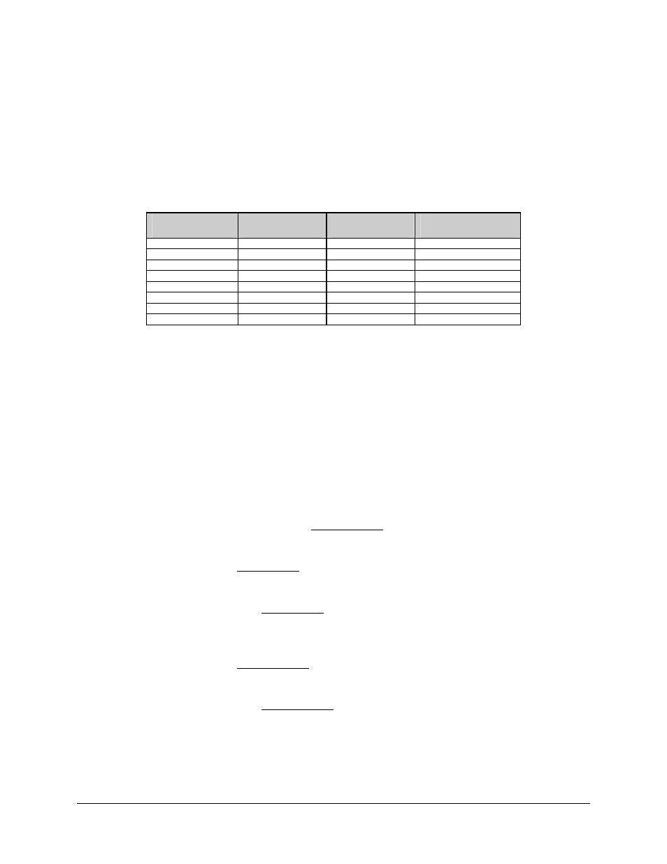
ASYNC Remote Operation
Remote modems can be controlled over the ASYNC channel from the local (or “hub”)
modem. Refer to Table 11-2 for a list of combinations:
Table 11-2.
ASYNC R
EMOTE
O
PERATION
Configuration #
Local
Modem
To Remote
Modem
Table #
1 EIA-232 EIA-232 Table
11
-3
2 EIA-232 EIA-485
(4-wire)
Table
11-4
3 EIA-232 EIA-485
(2-wire)
Table
11-5
4 EIA-485
(4-wire)
EIA-232 Table
11-6
5
EIA-485 (4-wire)
EIA-485 (4-wire)
Table 11-7
6
EIA-485 (4-wire)
EIA-485 (2-wire)
Table 11-8
7 EIA-485
(2-wire)
EIA-232 Table
11-9
8
EIA-485 (2-wire)
EIA-485 (4-wire)
Table 11-10
For each of the above combinations, front panel control settings and pinouts for local and
remote cables are listed in the following sections:
Before remote ASYNC communications can be implemented, the following must occur:
• At both the local and remote modems, front panel configuration
parameters must be set for each type of configuration.
• Industry-standard cables must be used at both modems.
To implement remote ASYNC operation, use the configuration information found in the
applicable section and perform the following steps:
1. Set the jumpers on the remote modem M&C/Display PCB according to the
information found in the applicable configuration section.
2. Set the local modem front panel controls according to the information found in
the applicable configuration section.
3. Connect the local modem 25-pin ASYNC connection (via breakout panel or Y
cable) to the terminal using the pinout information found in the applicable
configuration section. Refer to Figure 11-2.
4. Set the remote modem front panel controls according to the information found
in the applicable configuration section.
5. Connect the remote modem 25-pin ASYNC connection (via breakout panel or Y
cable) to the 9-pin J6 port at the rear of the modem using the pinout information
found in the applicable configuration section. Refer to Figure 11-2 and Figure
11-3.