Comtech EF Data SDM-300A User Manual
Page 86
SDM-300A Satellite Modem
Revision 6
External Connections
MN/SDM300A.IOM
4–8
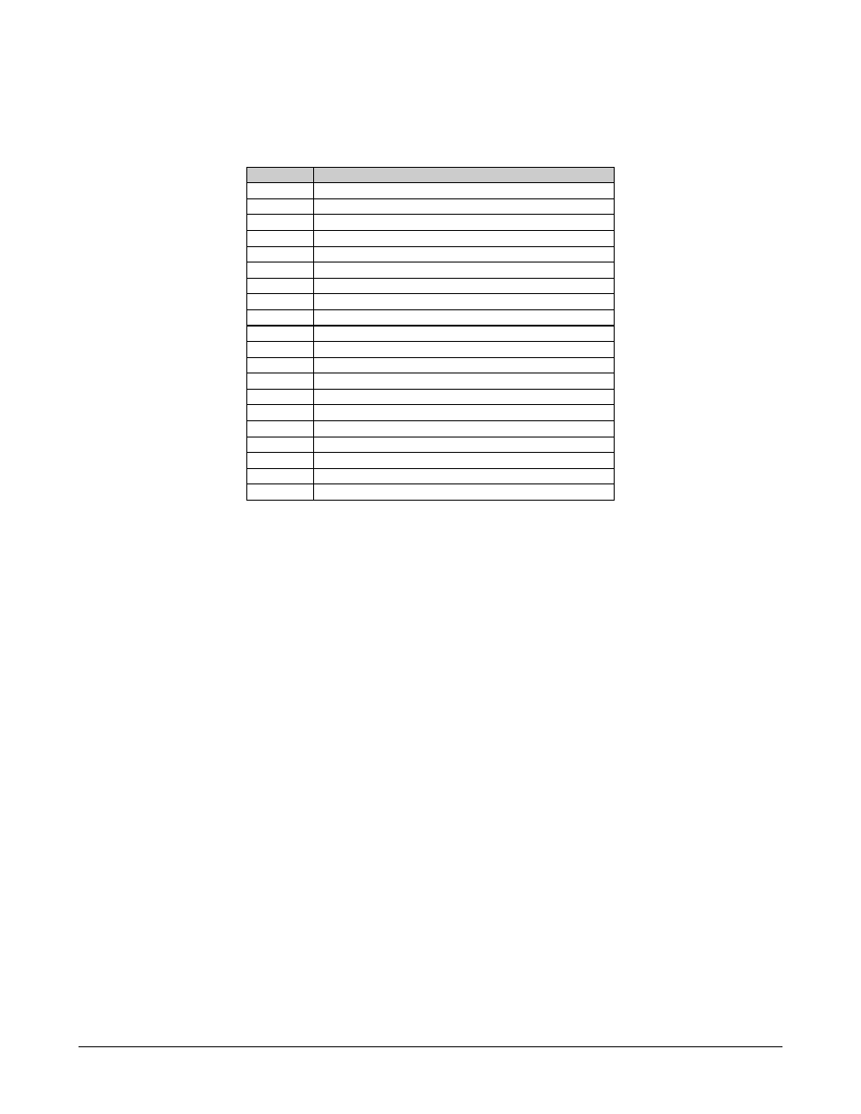
Table 4-5. 34-Pin Winchester Connector Pinouts (V.35)
Pin #
Name
A Ground
B Ground
C
Request to Send (RTS)
D
Clear to Send (CTS)
E
Data Set Ready (DSR)
F
Receive Line Signal Detect (RLSD)
P
Send Data A (SD-A)
R
Receive Data A (RD-A)
S
Send Data B (SD+B)
T
Receive Data B (RD+B)
U
Serial Clock Transmit External A (SCTE-A)
V
Serial Clock Receive A (SCR-A)
W
Serial Clock Transmit External B (SCTE+B)
X
Serial Clock Receive B (SCR+B)
Y
Serial Clock Transmit A (SCT-A)
c (CC)
External Reference Clock A (EXC-A)
d (DD)
External Reference Clock B (EXC+B)
m (MM)
Modulator Fault (MF)
n (NN)
Demodulator Fault (DF)
a(AA)
Serial Clock Transmit B (SCT+B)
Note: Pins H, J, K, L, M, N, Z, a (AA), b (BB), e (EE), f (FF), h (HH), j (JJ), k (KK),
l (LL) have no connection.
The modem is available with a Winchester V.35 as the data I/O connector (PL/6032). There is a
jumper on the unit that either opens or closes the CC line. The interface is shipped with jumpers
in positions 2 and 3, because:
1. Comtech EF Data has determined that several locations use Fireberd
test equipment
and a conflict will occur if CC is connected between the modem and the Fireberd
.
2. Placing the jumper in positions 2 and 3 opens up the CC line, because the
TTC/Fireberd
test equipment interfaces use the line for DTE/DCE control.
3. Grounding pin CC at the Fireberd
interface will change the Fireberd to a DCE
device.
4. Comtech EF Data uses the CC and DD for the input master clock (same as the external
clock input to the modem). To input an external clock, change the jumper to positions 1
and 2 (the pin closest to the Winchester connector).