Comtech EF Data SDM-300A User Manual
Page 80
SDM-300A Satellite Modem
Revision 6
External Connections
MN/SDM300A.IOM
4–2
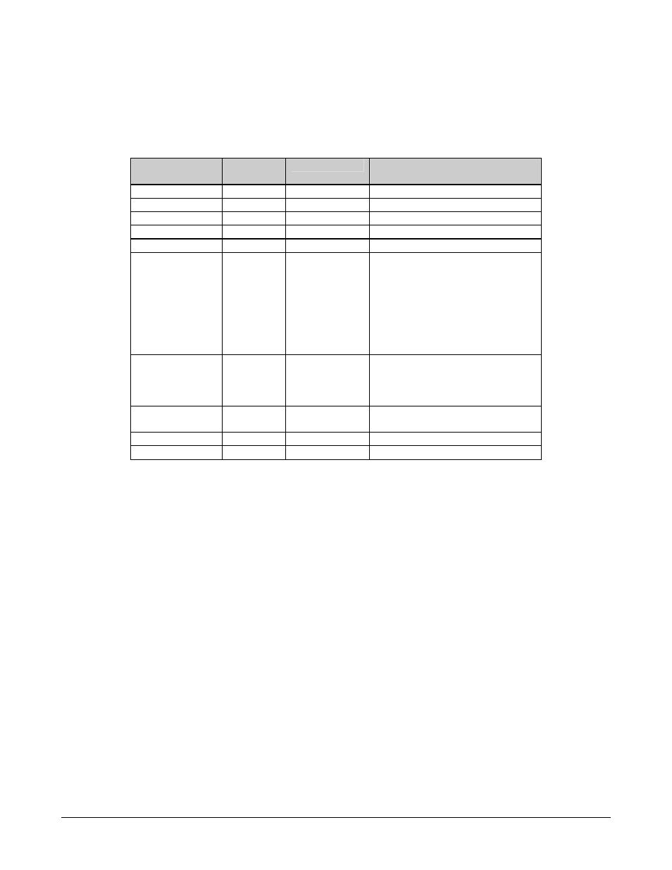
Table 4-1. Modem Rear Panel Connectors
Name
Ref. Desig.
Connector Type
Function
TX/IF OUTPUT
CP1
BNC
RF Output
RX/IF INPUT
CP2
BNC
RF Input
EXTERNAL REF
CP3
BNC
Input for EXT REF clock
REMOTE
J6
9-pin D
Remote Interface
FAULT
J7
9-pin D
FORM C Fault Relay Contacts
DATA I/O
J8
25-pin D
34-pin
37-pin D
50-pin D
50-pin D
100-pin D
15-pin D & BNC
Data Input/Output (standard modem)
V.35
RS-422
Data Input/Output (modem with
D&I/ASYNC/AUPC/IDR/IBS option)
Without Overhead Card
MUX option only
G.703 T1, E1/ASYNC Interface Adapter
AUX 1
J9
9-pin D
(TTL) Faults
Satellite Clock
Demod I/Q
Automatic Gain Control (AGC) Out
ALARMS
J10
9-pin D
FORM C Alarm
Relay Contacts
AC INPUT
NONE
IEC
Modem Power
GROUND NONE
10-32
Stud
Grounding
Note: The European EMC Directive (EN55022, EN50082-1) requires using properly shielded
cables for DATA I/O. These cables must be double-shielded from end-to-end, ensuring a
continuous ground shield.