Remote connector and pinouts (j6), 1 remote connector and pinouts (j6) – Comtech EF Data SDM-300A User Manual
Page 82
SDM-300A Satellite Modem
Revision 6
External Connections
MN/SDM300A.IOM
4–4
4.1.1
Remote Connector and Pinouts (J6)
The remote connector is a 9-pin subminiature female D connector (J6) located on the rear panel of
the modem. Screw locks are provided for mechanical security of the mating connector.
The remote connector interfaces the M&C functions to a remote location. The remote location can
be an M&C computer located away from the modem, but attached via cable to the remote
connector. This DCE interface is user selectable for either RS-232 or RS-484. Refer to Appendix
A for a description of the remote interface commands.
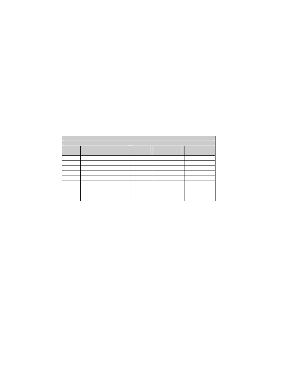
Refer to Table 4-2 for pinout information.
Table 4-2. Remote Connector and Pinouts (J6)
Pinout
RS-232
RS-485
Pin #
Name
Pin #
Name
(2-Wire)
Name
(4-Wire)
1 1
GND
2 RD
(RX) 2
3 TD
(TX) 3
4 4*
+RX/TX
+TX
5 GND 5*
-RX/TX
-TX
6 DSR 6
7 RTS 7
8 CTS 8*
+RX/TX
+RX
9 9*
-RX/TX
-RX
*For 2-Wire Operation:
• Only two wires are required.
• Tie pins 4 and 8 together (both +).
• Tie pins 5 and 9 together (both -).