Agc output, Interface specifications, Transmit clock source – Comtech EF Data SDM-300A User Manual
Page 380: Send clock timing source
SDM-300A Satellite Modem
Revision 6
Specifications
MN/SDM300A.IOM
19–24
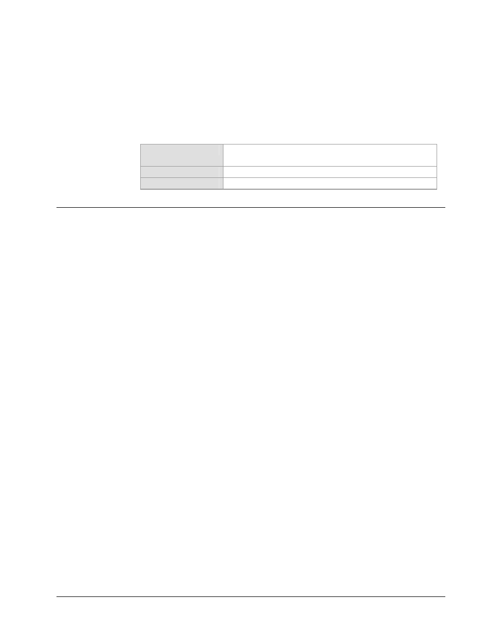
19.7.3 AGC
Output
A programmable DC output, proportional to the receive signal level, is located on the rear
panel at 10 mA maximum (0 to 10 volts).
Default Level
0 volts for –60 dBm
10 volts for –25 dBm
Low Level (0V)
Programmed from 0 to 10V in 0.5V increments.
High Level (10V)
Programmed from 0 to 10V in 0.5V increments.
19.8 Interface
Specifications
19.8.1 Transmit
Clock
Source
Select the TX clock from the following sources.
• Terrestrial:
± 100 PPM of the programmed rate, ≤ 5% jitter.
• SCT (internal):
± 10 PPM or SCT (with high stability option). ± 0.2 PPM.
19.8.2
Send Clock Timing Source
The send clock timing output can be generated from the Frequency Reference (either via the
front panel or remotely).
• If loop timing is selected the send clock timing output can be:
• The external clock input must be ± 100 PPM of the selected data rate.
• The RX satellite clock, RX data rate must be ± 100 PPM of the TX data rate.
• If the Asymmetrical Loop Timing (ASLT) option is selected, either via the front panel or
remotely, the send clock timing output can be referenced from:
• The external clock input, (Master Clock), which can be any multiple of 8 kHz as
long as it is
≥ 64 kHz ≤ 4.376 MHz or any multiple of 600 Hz as long as it is
≥ 2.4 kHz ≤ 64 kHz.
• The RX clock which can be any multiple of 8 kHz as long as it is ≥ 64 kHz ≤ 4.376
MHz or any multiple of 600 Hz as long as it is
≥ 2.4 kHz ≤ 64 kHz.