Duplex reed-solomon installation – Comtech EF Data SDM-300A User Manual
Page 70
SDM-300A Satellite Modem
Revision 6
Installation/Upgrades
MN/SDM300A.IOM
3–14
Duplex Reed-Solomon Installation:
1.
Disconnect the AC power to the unit.
2.
Remove the (2) side screws near the front of the modem. Slide top cover back and lift off.
*3.
Card 1 Removal, refer to Figure 3-6. If unit has top board (Card 1 – Overhead board), remove
the (4) rear panel screws around the 50-Pin I/O switch module. Unplug the I/O module, then
Remove the (7) mounting screws holding the Overhead board and carefully lift it off.
4.
Simplex Reed-Solomon removal, refer to Figure 3-6. Remove all Simplex Reed-Solomon
Boards if installed, from the SIMM sockets by pushing the spring clips outward while rocking
the board vertically, then lift out.
5.
Duplex Reed-Solomon installation, refer to Figure 3-7. Align the Duplex Reed-Solomon board
with either of the SIMM sockets while holding it nearly vertical with components toward Rear
Panel. Seat the connector into the socket and tilt the board toward the Front Panel until the
spring clips lock the board into place.
6.
Firmware installation, refer to Figure 3-7 If replacement
Firmware IC’s where sent with the Duplex Reed- Solomon Board,
Remove existing Firmware, U86 and U74 with PLCC type IC
puller. If puller not available, use ice pick type tool to alternately,
carefully pry upward at opposite corners of IC.
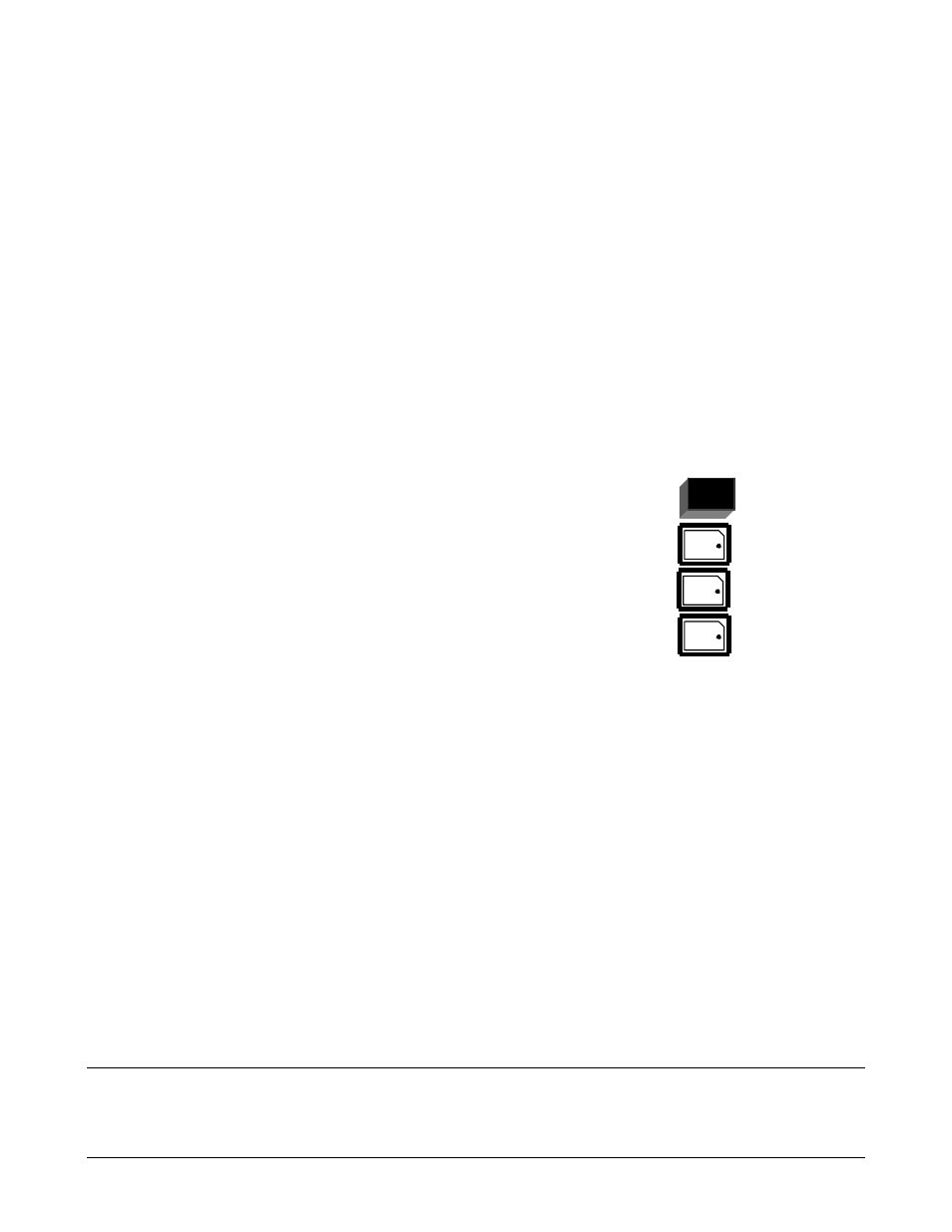
7.
Install the replacement Firmware, noting that the Dot mark should be oriented toward the
beveled corner of the socket before pushing the IC into the socket. U86 is located next to the
lithium battery NV-RAM (Large Black or Yellow IC, U95). U74 is located in the center socket
position.
*8.
If step #3 was required, re-install the Overhead board with its (7) mounting screws then re-plug
the I/O Module into the Rear Panel location and install its (4) mounting screws.
9.
Replace the Top Cover so forward edge mates under Front Panel lip. While holding in place, re-
install the (2) side screws.
10.
Turn on the AC power to the modem. Modem will re-initialize.
* Dependent steps – Other procedures shall be accomplished prior to performing steps indicated by an *.