Verilink 9000 Series (34-00271) Product Manual User Manual
Page 228
206
C
HAPTER
12: F
RAME
R
ELAY
P
ROTOCOL
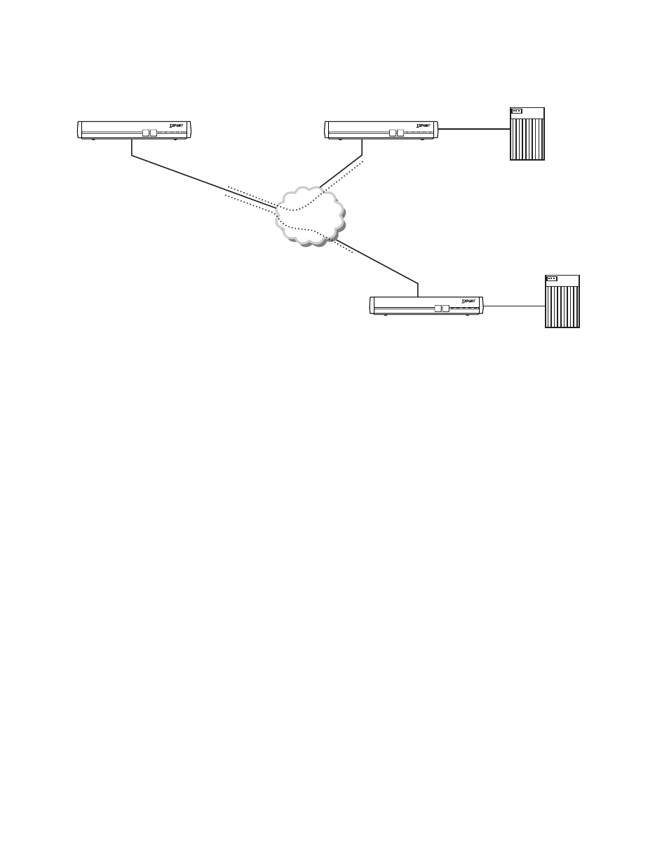
Figure 12-1 shows how multiple PVCs are established on the same physical link as
well as the fact that DLCIs are usually different on each side of the network:
If connectivity was needed between units 002 and 003, an additional PVC would
normally be established between these points. Since the TXPORT platform
performs switching functions, unit 001 can switch traffic between units 002 and
003.
Frame Relay
DOWNLOAD CONFIG
MODE BACKUP
NET
ALARM POWER
PRISM 9111
T
R
A
N
S
P
O
R
T
®
DOWNLOAD CONFIG
MODE BACKUP
NET
ALARM POWER
PRISM 9111
T
R
A
N
S
P
O
R
T
®
DOWNLOAD CONFIG
MODE BACKUP
NET
ALARM POWER
PRISM 9111
T
R
A
N
S
P
O
R
T
®
PVC 1 is a logical connection between units 001 and 002. DLCI 16 at unit 001 connects to DLCI 16 at Unit 002.
PVC 2 is a logical connection between units 001 and 003. DLCI 17 at unit 001 connects to DLCI 16 at Unit 003.
Unit 003
HOSTB
HOSTA
Unit 001
Unit 002
DLCI16
DLCI16
DLCI16
DLCI17
Figure 12-1 Typical Application Using Frame Relay