9111 port 1 dds option testing, Remote channel loop, Port 2 – Verilink 9000 Series (34-00271) Product Manual User Manual
Page 50
28
C
HAPTER
2: I
NSTALLATION
9111 Port 1
DDS Option
Testing
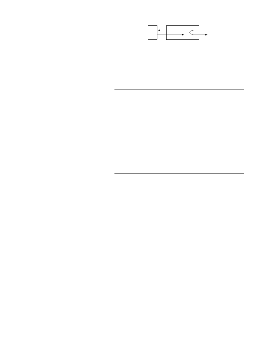
Remote Channel Loop
This loop is activated by
receiving a minimum of four
consecutive bytes of the
non-latching loopback code at
the proper data rate and remains looped as long as every other byte contains the
loopback code and continues for a minimum of four consecutive bytes after
receiving the last loopback code. Figure 2-8 shows the channel loop.
Port 2
Port 2 is a DTE
port. Its
interface is
RS-232 or V.35,
depending on a
jumper on the
main PCB. The
default is V.35.
To change this
jumper, see
Figure 2-9.
Table 2-13
shows the
pinout of Port 2.
DTE
NET
Figure 2-8 Channel Loop
Table 2-13 Port 2 Pinout
Signal
RS-232C
Circuit
Pin
V.35
Circuit
Pins
A/B
Shield Ground
AA
1
FG
1
Transmit Data
BA
2
SD
2/14
Receive Data
BB
3
RD
3/16
Request to Send
CA
4
RTS
4
Clear to Send
CB
5
CTS
5
Data Set Ready
CC
6
DSR
6
Signal Ground
AB
7
SG
7
Data Carrier Detect
CF
8
RLSD
8
Transmit Clock
DB
15
SCT
15/12
Receive Clock
DD
17
SCR
17/9
DTE Ready
CD
20
DTR
20
External Clock
DA
24
SCTE
24/11