9211 connections, Power supervisory port ethernet, Utp port – Verilink 9000 Series (34-00271) Product Manual User Manual
Page 54
32
C
HAPTER
2: I
NSTALLATION
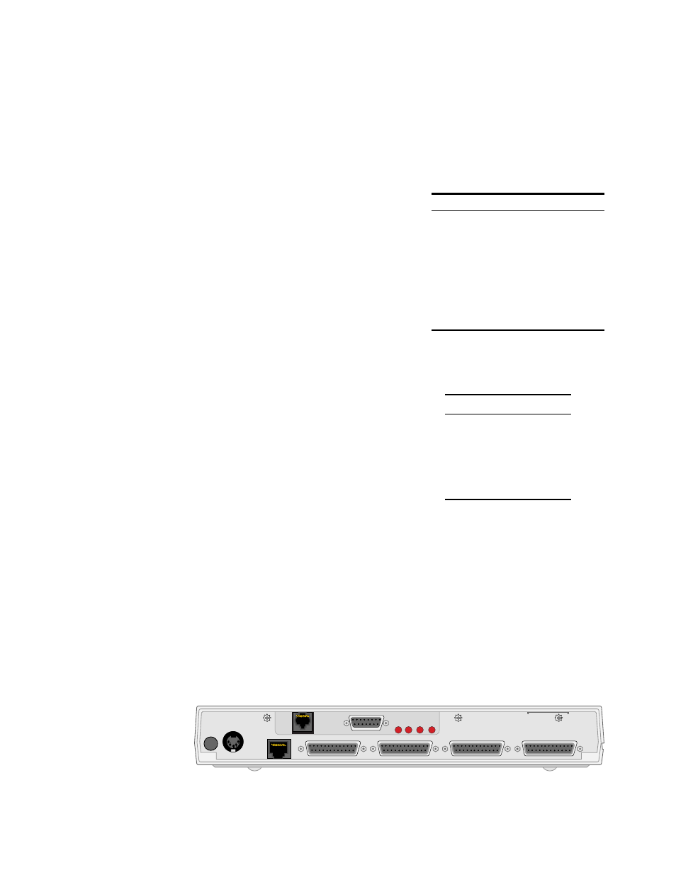
9211
Connections
Figure 2-12 shows the rear panels of the 9211, including the power connector;
reset button; UTP and AUI Ethernet connectors and LEDs; supervisory connector;
and connectors for ports 1 through 4.
Power
Connect the power supply [shown on page 20 (AC to DC) and page 21 (DC to
DC)] to the 9211. This applies power to the unit.
Supervisory
Port
The Supervisory port allows local, direct
connection of the unit to a dumb terminal or a
PC running a terminal emulation program
using the 9-9100-006-2 adapter and
9-1544-619-010 Supervisory cable. The form
factor of the connector is an RJ-48. Table 2-16
shows the pinout.
For remote applications, the Supervisory port
can also be connected to a modem using the
9-1544-619-010 cable and a 9-9100-005-1
adapter.
Ethernet
UTP Port
Table 2-17 shows the pinout of the Ethernet
port. The form factor of the connector is an
RJ-48.
PWR
RESET
ETHERNET
UTP
SUPV
PORT 1
PORT 2
PORT 3
PORT 4
LINK
COL
RXD
TXD
1
1
13
14
25
1
13
14
14
25
1
13
14
25
1
13
25
8
AUI
8
1
9
15
Figure 2-12 TXPORT 9211 Rear Panels and Power
Table 2-16 Supervisory Port Pinout
Pin
Signal
1
DTE Ready (DTR)
2
Clear to Send (CTS)
3
Signal Ground (SG)
4
Receive Data (RXD)
5
Transmit Data (TXD)
6
Frame Ground
7
Request to Send (RTS)
8
Data Set Ready (DSR)
Table 2-17 Ethernet Port Pinout
Pin
Signal
1
Data Out (+)
2
Data Out (-)
3
Data In (+)
4, 5, 7, 8
not used
6
Data In (-)