A connection example, Call request: userdata = hosta/01 call accept, Host – Verilink 9000 Series (34-00271) Product Manual User Manual
Page 26
4
C
HAPTER
1: G
ENERAL
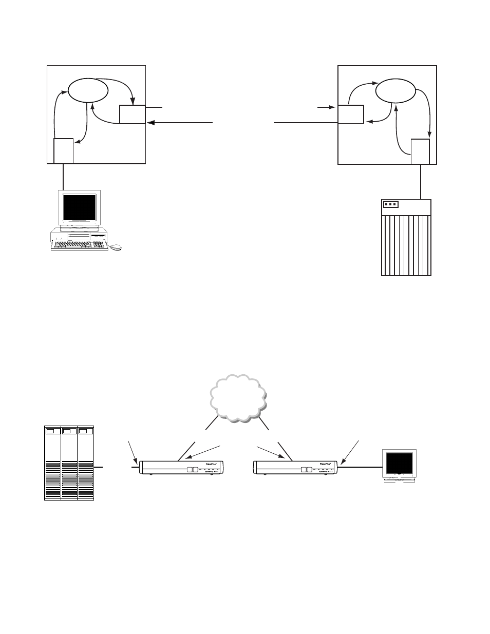
A Connection
Example
Figure 1-2 provides an example of how the MultiPro units establish connections. In
this example two 9111s are connected using the Frame Relay network via each
device’s Port 1. Unit 001 has a host device connected to port 3: unit 002 has a
terminal device connected to port 4. All address tables and endpoint checklists
have been configured as shown.
OS
X.25
Term
co
nn
co
nf
c
o
n
n
re
q
con
n
req
c
o
n
n
c
o
n
f
OS
X.25
Host
con
n
req
co
nn
re
q
co n
n
co n
f
c
o
n
n
c
o
n
f
Call request: userdata = HOSTA/01
Call accept
Processor
HOST
A
Address: 01
Default Host
Figure 1-1 Connection Request Process
HOST
HOSTA
DLCI 15
DLCI 16
PORTS 1
PORTS 4
PORTS 3
UNIT 001
UNIT 002
Frame Relay
Terminal
Address = AA
PORT 4 Configured as:
Poll/Select Terminal
Address List: [AA] Connect [HOSTA]
PORT 1 Configured as:
Frame Relay
Endpoint List: DLCI 16 [HOST]
PORT 1 Configured as:
Frame Relay
Endpoint List: DLCI 0015
[HOST]
PORT 3 Configured as:
Poll/Select Terminal
Host Name: [HOSTA]
DOWNLOAD CONFIG
MODE BACKUP
NET
ALARM POWER
DOWNLOAD CONFIG
MODE BACKUP
NET
ALARM POWER
Figure 1-2 9111 to 9111 Units Connected over Frame Relay