9111 connections, Power supervisory port ethernet, Port indicators – Verilink 9000 Series (34-00271) Product Manual User Manual
Page 46
24
C
HAPTER
2: I
NSTALLATION
9111
Connections
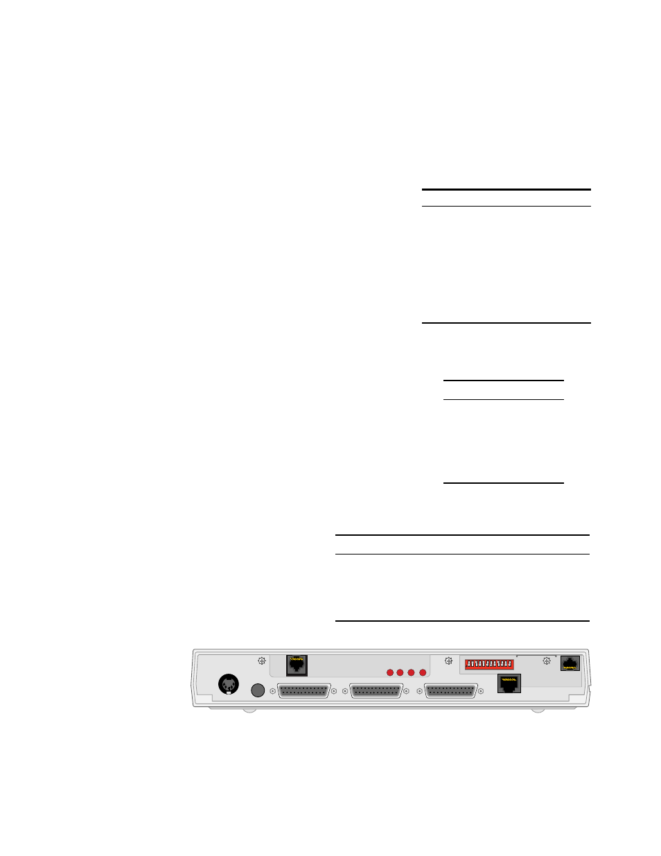
Figure 2-4 shows the rear panels of the 9111, including the power connector; reset
button; Ethernet connector and LEDs; supervisory connector; and connectors for
ports 1 through 4.
Power
Connect the power supply [shown on page 20 (AC to DC) and page 21 (DC to
DC)] to the 9111. This applies power to the unit.
Supervisory
Port
The Supervisory port allows local, direct
connection of the unit to a dumb terminal or a
PC running a terminal emulation program
using the 9-9100-006-2 adapter and
9-1544-619-010 Supervisory cable. The form
factor of the connector is an RJ-48. Table 2-6
shows the pinout.
For remote applications, the Supervisory port
can also be connected to a modem using the
9-1544-619-010 cable and a 9-9100-005-1
adapter.
Ethernet
Port
Table 2-7 shows the pinout of the Ethernet port.
Indicators
The Ethernet LED
indicators are located to the
right of the Ethernet
connector. Table 2-8 shows
how to interpret them.
Table 2-6 Supervisory Port Pinout
Pin
Signal
1
DTE Ready (DTR)
2
Clear to Send (CTS)
3
Signal Ground (SG)
4
Receive Data (RXD)
5
Transmit Data (TXD)
6
Frame Ground
7
Request to Send (RTS)
8
Data Set Ready (DSR)
Table 2-7 Ethernet Port Pinout
Pin
Signal
1
Data Out (+)
2
Data Out (-)
3
Data In (+)
4, 5, 7, 8
not used
6
Data In (-)
Table 2-8 Ethernet LED Interpretation
Indicator
Interpretation
TXD
The Ethernet port is transmitting data.
RXD
The Ethernet port is receiving data.
LINK
The unit is physically linked to a network.
COL
There is a data collision.
PWR
RESET
ETHERNET
SUPERVISORY
1
3
5
7
9 11
2
4
6
8 10 12
T1
PORT 2
PORT 3
PORT 4
TXD
RXD
LINK
COL
ON
1
2
3
4
5
6
7
8
9
10 11 12
Figure 2-4 9111 with Port 1 T1 Option