Programming 5 - 9 – Yaskawa E7L Drive Bypass User Manual
Page 101
Programming 5 - 9
Options - J, U, V or L "Serial Communications"; Bypass with serial communication for run/stop
control and speed monitoring:
Hand mode speed command from Keypad/Operator.
Auto mode speed command input signal, 0-10 VDC applied to Terminal TB3-3 (Drive terminal A2).
Auto mode run/stop command for Drive from serial communication.
Auto mode run/stop command for Bypass from serial communication.
Options - J, U, V or L and P "Serial Communications" and "Pneumatic Pressure Transducer";
Bypass with serial communication for run/stop control and speed monitoring, with pneumatic
input for speed control:
Hand mode speed command from Keypad/Operator.
Auto mode speed command input signal from the pneumatic transducer, or 4-20 mA applied to Terminal TB5-9
(Drive terminal A2).
Auto mode run/stop command for Drive from serial communication.
Auto mode run/stop command for Bypass from serial communication.
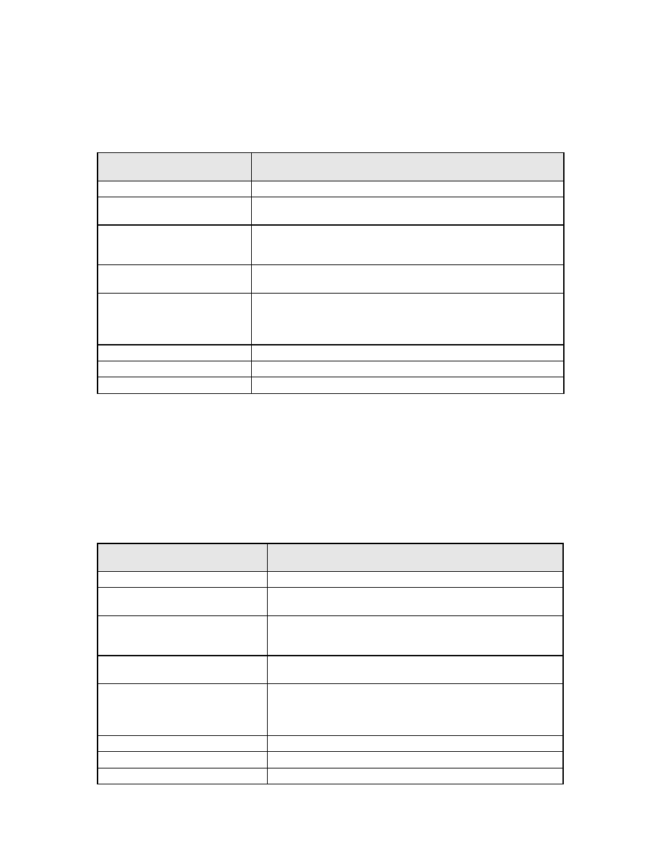
Significant
Parameter Setting
Drive Operational Result
b1-01 = 0: Operator
Speed command source = Keypad/Operator (d1-01)
H3-08 = 0: 0-10 VDC
Drive Terminal A2 is programmed for 0-10 VDC (Note – Control PCB DIP
switch S1-2 must also be OFF)
H3-09 = 2: Aux Reference (default)
Drive Terminal A2 function is set to be a speed command input. This setting
also gives terminal A2 priority over d1-02 for “preset speed 2”, see Program-
ming Manual TM.E7.02.
H1-02 = 3: Multi-Step Ref 1
DIP switch S4-2 must be ON
A Drive terminal S4 input contact closure selects A2 as “preset speed 2” speed
input. The S4 input closes when H/O/A = Auto.
H1-03 = 6C: Com/Inv Sel 2
A Drive terminal S5 input contact closure allows b1-01 to select d1-01
(keypad) as the speed command. An open contact selects serial com for the
run/stop command (the serial com speed command is overridden by the preset
speed above). This input contact is closed when H/O/A = Hand.
H5-02 = Baud Rate
Each protocol requires the baud rate indicated in Table 5.2
H5-07 = RTS Control
Each protocol requires the Request to Send control indicated in Table 5.2
H5-08 = Protocol Selection
Drive communicates via protocol selected. 0: Modbus, 1: N2 or 2: FLN
Significant
Parameter Setting
Drive Operational Result
b1-01 = 0: Operator
Speed command source = Keypad/Operator (d1-01)
H3-08 = 2: 4-20 mA (default)
Drive Terminal A2 is programmed for 4-20 mA (Transducer output is 4-20
mA) (Note – Control PCB DIP switch S1-2 must also be ON)
H3-09 = 2: Aux Reference (default)
Drive Terminal A2 function is set to be a speed command input. This set-
ting also gives terminal A2 priority over d1-02 for “preset speed 2”, see
Programming Manual TM.E7.02.
H1-02 = 3: Multi-Step Ref 1
DIP switch S4-2 must be ON
A Drive terminal S4 input contact closure selects A2 as “preset speed 2”
speed input. The S4 input closes when H/O/A = Auto.
H1-03 = 6C: Com/Inv Sel 2
A Drive terminal S5 input contact closure allows b1-01 to select d1-01
(keypad) as the speed command. An open contact selects serial com for the
run/stop command (the serial com speed command is overridden by the
preset speed above). This input contact is closed when H/O/A = Hand.
H5-02 = Baud Rate
Each protocol requires the baud rate indicated in Table 5.2
H5-07 = RTS Control
Each protocol requires the Request to Send control indicated in Table 5.2
H5-08 = Protocol Selection
Drive communicates via protocol selected. 0: Modbus, 1: N2 or 2: FLN