Hunting prev, N1-01, Hunting prevention selection – Yaskawa E7L Drive Bypass User Manual
Page 235: Hunt prev select, Disabled (hunting prevention function disabled), Enabled (hunting prevention function enabled), 0 or 1, Programming, N1-02, Hunting prevention gain setting
Parameters A - 23
Hunting Prev
n1-01
Hunting Prevention Selection
Hunt Prev Select
0: Disabled (Hunting prevention function disabled).
1: Enabled (Hunting prevention function enabled).
If the motor vibrates while lightly loaded, hunting
prevention may reduce the vibration. There is a loss of
responsiveness if hunting prevention is enabled.
0 or 1
1
Programming
n1-02
Hunting Prevention Gain Setting
Hunt Prev Gain
Gain setting for the Hunting Prevention Function.
If the motor vibrates while lightly loaded and n1-01=1,
increase the gain by 0.1 until vibration ceases.
If the motor stalls while n1-01=1 decrease the gain by
0.1 until the stalling ceases.
0.00 to 2.50
1.00
Programming
High Slip
n3-01
High-Slip Braking Deceleration
Frequency Width
HSB Decel Width
Sets how aggressively the drive decreases the output
frequency as it stops the motor. If overvoltage (OV)
faults occur during HSB, this parameter may need to be
increased.
1 to 20
5%
Programming
n3-02
High-Slip Braking Current Limit
HSB Current Ref
Sets the maximum current to be drawn during a HSB
stop. Higher n3-02 settings will shorten motor stopping
times but cause increased motor current, and therefore
increased motor heating.
100 to 200
150%
Programming
n3-03
High-Slip Braking Dwell Time at
Stop
HSB DwelTim@ Stp
Sets the amount of time the Drive will dwell at E1-09
(Minimum Frequency). If this time is set too low, the
machine inertia can cause the motor to rotate slightly
after the HSB stop is complete and the Drive output is
shut off.
0.0 to 10.0
1.0sec
Programming
n3-04
High-Slip Braking Overload Time
HSB OL Time
Sets the time required for a HSB Overload Fault to
occur when the Drive output frequency does not change
for some reason during a HSB stop. Normally this does
not need to be adjusted.
30 to 1200
40sec
Programming
Monitor Select
o1-01
User Monitor Selection
User Monitor Sel
Selects which monitor will be displayed upon power-up
when o1-02 = 4.
6 to 53
6
Programming
o1-02
User Monitor Selection After
Power-Up
Power-On Monitor
Selects which monitor will be displayed upon
power-up.
1: Frequency Ref
2: Output Freq
3: Output Current
4: User Monitor (set by o1-01)
1 to 4
1**
Programming
o1-03
Digital Operator Display Selection
Display Scaling
0 to 39999
0
Programming
o1-05
LCD Brightness Adjustment
LCD Contrast
0 to 5
3
Programming
** Factory setting changes to “2” when b5-01=1
Table A.1 Parameter List (Continued
)
Parameter
No.
Parameter Name
LCD Digital Operator Display
Description
Setting
Range
Factory
Setting
Menu
Location
Sets the units of the Frequency References (d1-01
through d1-17) and the Frequency Reference Monitor
(U1-01).
0: Hz
1: % (100%. = E1-04)
2 to 39: RPM. (Enter the number of motor poles.)
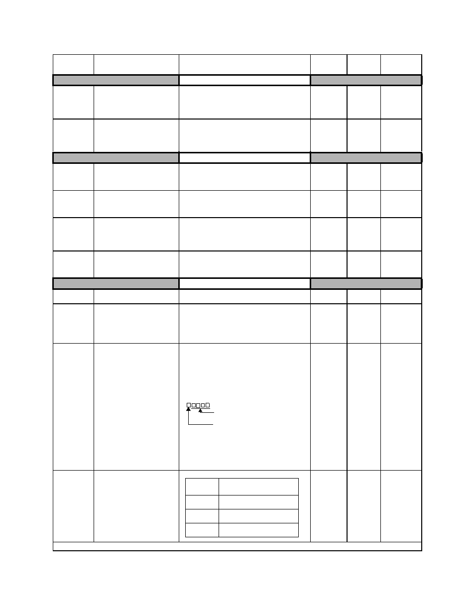
40 to 39999: User display
Desired set/display value is set at Max.
output frequency.
4 digit number.
The number of digits from the right
the decimal point is displayed.
Example: If “200.0 is displayed at Max. output
frequency, set “12000”.
When o1-03
≥40 (user units), the unit selected in
o1-09 will be displayed for D1-01 to D1-17, U1-01,
U1-02, and U1-20
Set Value
Description
5
LCD display becomes dark
3
Standard setting
1
LCD display becomes light