Dip switch selectable functions – Yaskawa E7L Drive Bypass User Manual
Page 26
Physical Installation 1 - 14
DIP Switch Selectable Functions:
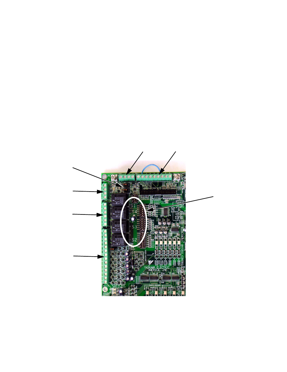
The DIP switches used to select these functions are located on the logic controller Printed Circuit Board (PCB) A2 (See Figure
1.9). The factory default is shown on the wiring diagram in Chapter 2 or Schematic diagram E7L-00.
DIP switches S1, S2, S3 and S4 allow the user to configure various project specific functions of the E7L including:
• Serial Communication terminating resistor
• Speed command source
• Analog input signal level
• Activate or inactivate functions:
Auto transfer to Bypass on Drive Fault
Safety interlock circuit
BAS interlock circuit
• Power-up mode selection
• Function of 3 SPDT programmable output relays:
Annunciate Running in Bypass mode
Damper actuator energized - employed to energize damper actuator
Annunciate Auto-Transfer to Bypass
Annunciate Running in Drive mode
Annunciate Run command received from serial comm
Annunciate Hand mode
Annunciate Auto mode
Annunciate Drive, motor or control fault
Fig 1.9 Printed Circuit Board A2, DIP Switches for Drive/Bypass Operational Configuration
DIP Switch
Location on
PCB A2
TB5
TB4
TB3
TB2
TB1
J2 and J3