Setting, Programming 5 - 24 – Yaskawa E7L Drive Bypass User Manual
Page 116
Programming 5 - 24
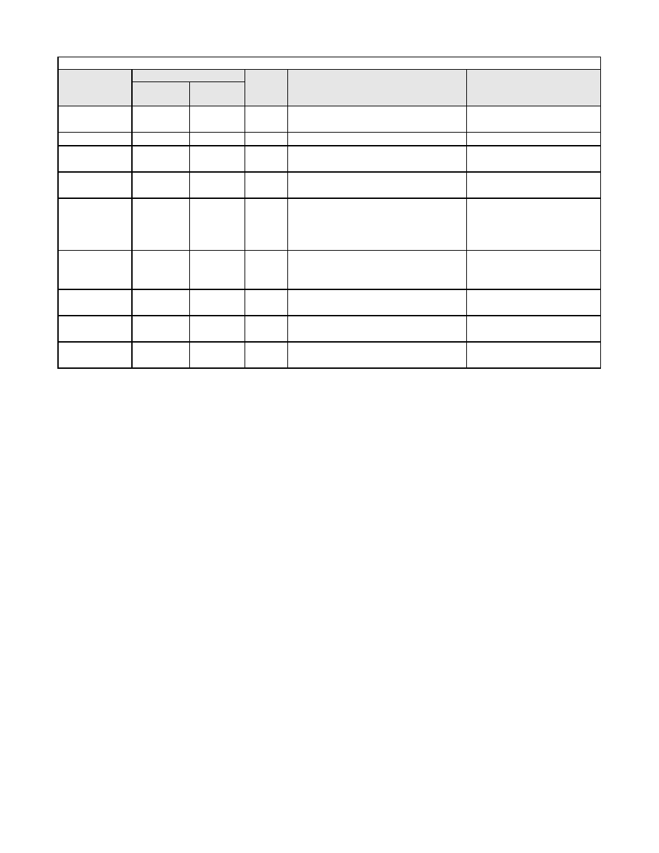
Table 5.3 PI Control Parameter Settings in E7L Bypass Units
PARAMETER
NUMBER
SETTING
UNITS
DESCRIPTION
OPTIONAL LCD
KEYPAD DISPLAY
For Bypass Setting
Bypass & PI
Control
Bypass
Default
b1-01
0
SEE TABLE
5.2
N/A
Frequency Reference Selection – Selects the
speed command input source
Reference Source / Terminals
b5-01
1
0
N/A
PI Mode Selection – Enables PI mode
PI Mode Setting / PI Mode
H1-03
SEE TABLE
5.4
SEE TABLE
5.2
N/A
Drive Terminal S5 Function Selection – Set
for various operating modes
Terminal S5 Sel / Com/Inv Sel 2,
for example
H1-04
SEE TABLE
5.4
4
N/A
Drive Terminal S6 Function Selection – Set
for PI Disable, turn off PI controller
Terminal S6 Sel / PI Disable
H3-08
SEE TABLE
5.4
SEE TABLE
5.2
N/A
Drive Terminal A2 Signal Level – Signal
selection, 0 to 10 VDC (Drive control board
switch S1-2 off) or 4 to 20 mA (Drive con-
trol board switch S1-2 on)
Term A2 Signal / 0-10 VDC
H3-09
B
SEE TABLE
5.2
N/A
Drive Terminal A2 Function Selection –
Selects how this input will be used by the
Drive
Terminal A2 Sel / PI Feedback
H5-02
SEE TABLE
5.4
3
N/A
Serial Communication Speed Selection,
Baud Rate
Serial Baud Rate/
9600 Baud
H5-07
SEE TABLE
5.4
1
N/A
Serial Communication Request to Send
Control
RTS Control Sel/enabled
H5-08
SEE TABLE
5.4
0
N/A
Serial Communication Protocol Selection
Protocol Select/N2 (Metasys)