Removing the drive cooling fan assembly, Remove the cooling fan(s) from the fan assembly, Mounting the drive cooling fan assembly – Yaskawa E7L Drive Bypass User Manual
Page 208: Fig 7.3 cooling fan assembly replacement procedure
Maintenance 7 - 6
Drive Models CIMR-
_
_ _
2022 thru 2110 (30 HP and above @ 208V/240V)
and 4030 thru 4300 (40 HP and above @ 480V)
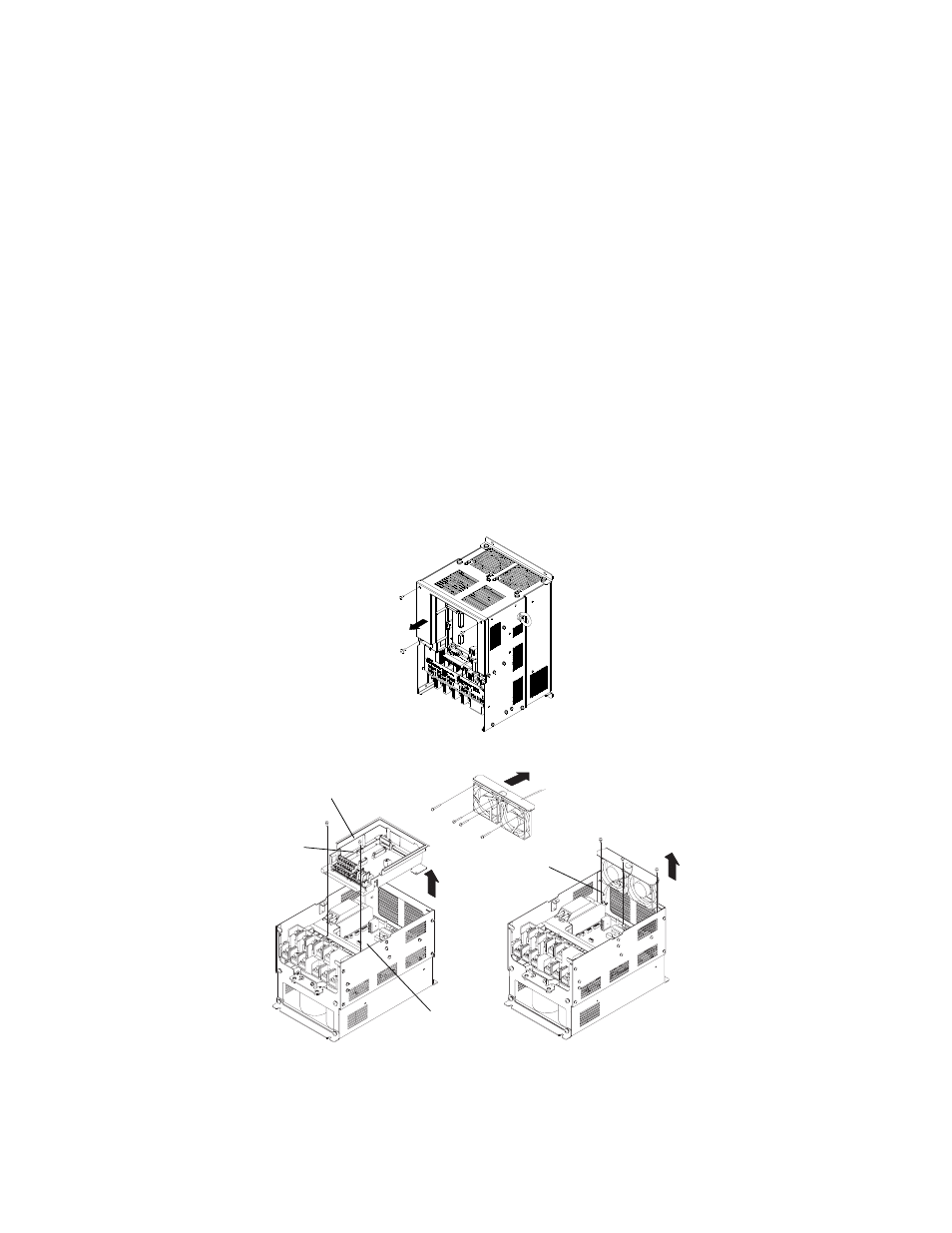
A cooling fan assembly is attached to the top inside the Drive. The cooling fan assembly includes the heat sink cooling fans
and the internal cooling fan. The cooling fan(s) can be replaced without removing the Drive from the enclosure panel.
Removing the Drive Cooling Fan Assembly
1. Always turn OFF the input power before removing and installing the heatsink cooling fan assembly.
2. Remove the terminal cover, Drive cover, Digital Operator, and front cover from the front of the Drive.
3. Remove the Control PCB bracket (if necessary) to which the cards are mounted. Remove all cables connected to the
Control PCB and remove the cooling fan power connector from the fan board (13 PCB) positioned near the top of the
Drive.
4. Remove the cooling fan power connectors from the gate Drive board (3PCB) positioned at the back of the Drive.
5. Remove the fan assembly screws and pull out the fan assembly from the Drive.
6. Remove the cooling fan(s) from the fan assembly.
Mounting the Drive Cooling Fan Assembly
After attaching a new cooling fan, reverse the above procedure to attach all of the components.
When attaching the cooling fan to the mounting bracket, be sure that the air flow goes toward the top of the Drive.
Fig 7.3 Cooling Fan Assembly Replacement Procedure
Air flow direction
Gate driver
Connector
Fan cover
Control PCB
Control PCB bracket