Fig 5.23 custom v/f pattern programming curve, E2 motor setup, E2-01 motor rated current – Yaskawa E7L Drive Bypass User Manual
Page 139
Programming 5 - 47
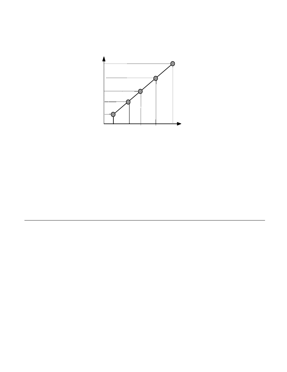
To set up a custom V/f pattern, program the points shown in the diagram below using parameters E1-04 through E1-13. Be sure
that the following condition is true:
E1-09
≤ E1-07 ≤ E1-06 ≤ E1-11 ≤ E1-04
Fig 5.23 Custom V/f Pattern Programming Curve
Increasing the voltage in the V/f pattern increases the available motor torque. However, when setting a custom V/f pattern,
increase the voltage gradually while monitoring the motor current, to prevent:
•
Drive faults as a result of motor over-excitation
•
Motor overheating or excessive vibration
E2 Motor Setup
E2-01 Motor Rated Current
Setting Range:
Model Dependent (see appendix B)
Factory Default: Model Dependent
The Motor Rated Current parameter (E2-01) is necessary information for the Drive motor protection function. The motor over-
load protection parameter L1-01 is enabled by default. In addition, motor rated current is used by the torque compensation func-
tion to insure optimum torque production. Set E2-01 to the full load amps (FLA) value stamped on the motor’s
nameplate. During Auto-tuning, it is required for the operator to enter the motor rated current in parameter T1-04 on the
Auto-Tuning menu. If the Auto-tuning operation completes successfully, the value entered into T1-04 will be also written into
E2-01.
For applications employing a Drive that is oversized for the motor, E2-01 may be set as low as 10% of the Drive output current
rating. The ampere value in E2-01 however, must always be greater than the “No Load Current” value in parameter E2-03 or an
OPE02 error will be displayed.
Frequency
E1-09 E1-07
E1-06
E1-04
E1-11
Max Voltage E1-05
Mid Voltage B E1-12
Mid Voltage A E1-08
Base Voltage E1-13
Min Voltage E1-10
Min
Freq
Max
Freq
Base
Freq
Mid
Freq
A
Mid
Freq B
Freq A