H3-08 drive terminal a2 signal level, Fig 5.28 dip switch s1, Programming 5 - 56 – Yaskawa E7L Drive Bypass User Manual
Page 148
Programming 5 - 56
H3-08 Drive Terminal A2 Signal Level
H3-08 is one of the special parameter settings required by the Bypass logic circuit. See Table 5.2.
The H3-08 parameter (Drive Terminal A2 Signal Level) allows the programmer to specify the signal that will be applied to the
A2 analog input (E7L Terminal TB3-3 or TB5-9). The A2 analog input can accept either a 0–10 Vdc or 4-20 mA signal as a
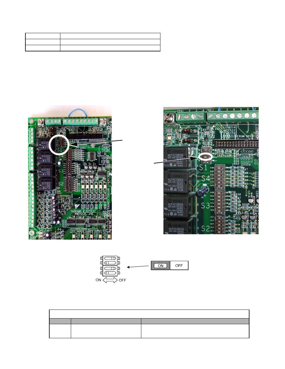
reference. The E7L also has a DIP switch (S1) on the PCB A2 that must be set for the proper reference signal into the A2
analog input. The S1-2 DIP switch setting determines the internal resistance of the Drive A2 input while parameter H3-08
determines how the Drive interprets the measured signal.
Fig 5.28 DIP Switch S1
Setting
Description
0
0 - 10VDC
2
4 - 20mA (Default)
Table 5.15 DIP Switch S1-2
Name
Function
Setting
S1-2
Input signal for Drive analog input A2
OFF: 0 to 10 V (internal resistance: 20 k
Ω)
ON: 4 to 20 mA (internal resistance: 250
Ω) (Factory default)
DIP Switch S1 example
2
3
4
1
O
Location of S1
S1-2