Bypass control circuit terminal functions, Table 2.15 bypass control circuit terminals, Electrical installation 2 - 20 – Yaskawa E7L Drive Bypass User Manual
Page 52
Electrical Installation 2 - 20
Bypass Control Circuit Terminal Functions
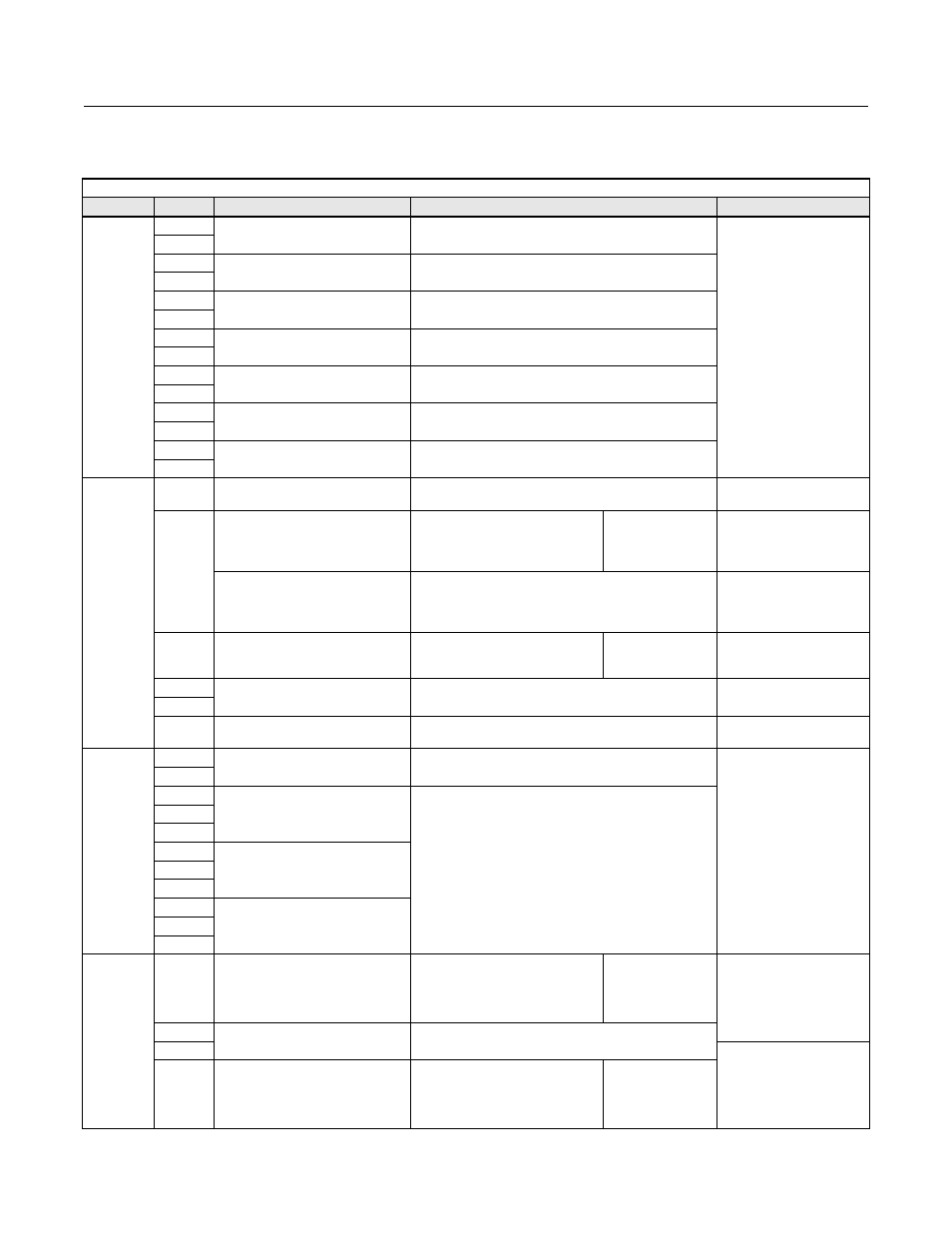
The functions of the control circuit terminals are shown in Table 2.15.
Table 2.15 Bypass Control Circuit Terminals
Type
No.
Signal Name
Function
Signal Level
Digital
input
signals
TB1-1
NC Safety Circuit
Fault when OPEN
Dry
Contacts
TB1-9
TB1-2
Auto Mode run/stop command
Run when CLOSED; stopped when OPEN.
TB1-9
TB1-3
BAS Interlock
Enable Drive when Closed
TB1-9
TB1-4
Remote Transfer
Transfer to Bypass when Closed
TB1-9
TB1-5
Smoke Purge
Transfer to Bypass when Closed
TB1-9
TB5-4
Drive Input Terminal S7
Programmable Input
TB5-2
TB5-5
Drive Input Terminal S6
Programmable Input
TB5-2
Analog
input
signals
TB3-2
+15 VDC power supply
+15 VDC power supply for analog Transmitters
+15 VDC
(Max. current: 20 mA)
TB3-3
Analog input or Speed Command
when connected to Drive
Terminal A2 by DIP switches
S1-3 and S1-4
4 to 20 mA/100% or 0 to +10
VDC/100%
(H3-08 and DIP switch S1-2)
Function set by
H3-09.
4 to 20 mA(250
Ω)
0 to +10 V(20 k
Ω)
Analog Input or Speed Command
when connected to Drive
Terminal A1 by DIP switches
S1-3 and S1-4
0 to +10 VDC/100%
0 to +10 V(20 k
Ω)
TB5-9
Multi-function analog input
connected to Drive terminal A2
4 to 20 mA/100% or 0 to +10
VDC/100%
(H3-08 and DIP switch S1-2)
Function set by
H3-09.
4 to 20 mA(250
Ω)
0 to +10 V(20 k
Ω)
TB3-1
Analog input common
–
–
TB5-7
PE
Shield wire, optional ground line
connection point
–
–
Digital
output
signals
TB1-10
Motor Run
CLOSED During Motor Operation
Dry contacts
Contact capacity:
5 A max. at 250 VAC
5 A max. at 120 VAC
TB1-11
TB1-12
Programmable Relay 1
Form C Relay Function Selections:
1. Bypass Run
2. Damper Actuator
3. Auto Transfer
4. Drive Run
5. Serial Com. Run
6. Hand Mode
7. Auto Mode
8. System Fault
See Table 2.6 for DIP Switch programming
TB1-13
TB1-14
TB2-1
Programmable Relay 2
TB2-2
TB2-3
TB2-4
Programmable Relay 3
TB2-5
TB2-6
Analog
output
signals
TB3-4
Multi-function analog output
(Drive terminal FM)
Frequency Output
0 to +10 VDC/100% frequency
Multi-function
analog monitor 1
Function set by
H4-01
0 to +10 VDC or 4-20
mA set by Jumper J2
and H4-07
TB3-1
Analog output common
–
TB5-7
0 to +10 VDC or 4-20 mA
set by Jumper J3
and H4-08
TB5-6
Multi-function analog output
(Drive terminal AM)
Current Monitor
0 to +10 VAC/100%
Drive's rated current
Multi-function
analog monitor 2
Function set by
H4-04