Bypass unit operation description, Start up and operation 4 - 10 – Yaskawa E7L Drive Bypass User Manual
Page 88
Start Up and Operation 4 - 10
Bypass Unit Operation Description
(For selector key positions, control inputs and DIP switch selectable functions.)
The Bypass has two modes of operation: Bypass and Drive. When in the Bypass mode the connected motor is run directly
from the incoming AC line, whereas in Drive mode the motor is run from the Drive output. The DRIVE Select and Bypass
Select keys located on the front panel determine the operating mode. Within each operating mode are two methods of control;
HAND and AUTO. The HAND/OFF/AUTO selector keys on the front panel determine this control method.
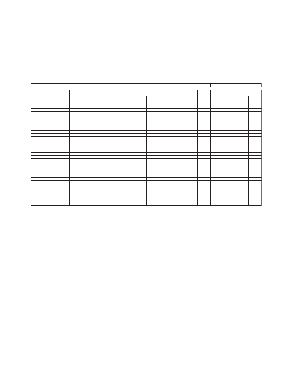
Table 4.1 provides a look at various combinations of the control panel selector key positions, control inputs to TB1 through
TB5 and the status of the DIP switch selectable functions.
1
O
Drive
0
0
D
E
X
E
X
X
None
2
O
Drive
0
0
D
E
0
X
None
On
3
O
Drive
0
0
D
X
E
0
X
None
4
H
Drive
0
0
D
X
E
0
X
None
On
5
H
Drive
0
0
D
X
X
X
Drive
6
H
Bypass
N
0
0
D
X
X
X
Bypass
7
H
Bypass
T
0
0
D
X
X
X
Bypass
8
H
Bypass
N
0
0
D
E
0
E
0
X
None
On
9
H
Bypass
N
0
0
D
X
E
0
X
None
On
10
H
Drive
X
0
D
X
X
X
X
Bypass
On
11
H
Drive
0
X
D
X
Bypass
12
H
Drive
0
0
E
X
X
X
X
Bypass
Flash
13
H
Drive
0
0
E
0
X
X
X
Drive
14
A
Drive
0
0
0
D
X
X
X
None
15
A
Drive
X
0
0
D
X
X
X
Drive
On
On
On
16
A
Drive
X
0
0
D
E
0
X
None
On
17
A
Drive
X
0
0
D
X
E
0
X
None
On
On
18
A
Drive
X
X
0
D
X
X
X
X
X
Bypass
On
On
19
A
Drive
X
0
X
D
X
Bypass
On
20
A
Drive
X
0
0
E
X
X
X
X
Bypass
Flash
On
21
A
Bypass
N
X
0
0
D
X
X
X
Bypass
On
22
A
Bypass
T
X
0
0
D
X
X
X
Bypass
On
23
A
Bypass
N
X
0
0
D
E
0
X
None
On
24
A
Bypass
N
X
0
0
D
X
0
X
None
On
On
25
A
Bypass
N
X
0
X
D
X
X
X
Bypass
On
26
O
Drive
0
X
D
X
X
X
Bypass
27
O
Bypass
N
0
X
D
X
X
X
Bypass
28
A
Drive
X
0
0
D
X
X
0
None
On
29
A
Bypass
N
X
0
0
D
X
X
0
None
On
30
H
Drive
0
0
D
X
X
0
None
31
O
Drive
0
0
D
D
D
X
None
32
H
Bypass
N
0
0
D
D
D
X
Bypass
33
A
Drive
X
0
0
D
D
D
X
Drive
On
Note: A blank cell indicates the input can be in any of the possible positions (don’t care).
Definitions:
TB = Terminal Block
SX-X = DIP Switch Number
X = Closed Input Contacts
0 = Open Input Contacts
D = Disabled
Drive or
Bypass
Select
Test/
Normal
Auto
Run
TB1 2&9
TB1 1&9
Motor O/L
Operating
Mode
Result
Remote
Xfer
TB1 4&9
DIP
S2-1
Drive
Fault
DIP
S2-7
Smoke
Purge
TB1 5&9
DIP
S2-8
TB1 3&9
Table 4.1 E7L 2 Contactor Bypass Inputs and Operating Modes
System
Auto Xfer
Safety
Damper/BAS
Control Panel LEDs
Selector Buttons
Contact Closure Inputs
DIP Switch Selectable Functions
H/O/A
Select
Status LEDs
Safety
Open
Auto/Rem
Xfer
Damper/
BAS
Auto Run