Bypass unit start up procedure, Fig 4.1 typical motor overload and contactors – Yaskawa E7L Drive Bypass User Manual
Page 83
Start Up and Operation 4 - 5
BYPASS UNIT START UP PROCEDURE
(Please review “Bypass Start Up Preparation” on page 4-4)
The front control panel has a digital alpha/numeric display and keypad, in the upper portion, for Drive operation and program-
ming. The row of LEDs above the alpha/numeric display indicate Drive operational status. The REMOTE SEQ and REF
LEDs in this row are always lit in most Bypass unit applications of the E7 Drive (See Chapter 3 for an explanation). The row
of LEDs below the alpha/numeric display indicate the Drive menu that is presently active.
The lower portion of the front control panel displays the operating mode status via LEDs and controls the HAND/OFF/AUTO
functions for both the Drive and Bypass. The general rule for LED colors, in the lower portion of the control panel, is:
Green = Normal Status
Amber = Abnormal Status
Red
= Fault Status
1. Before applying power, make sure that the following conditions are met:
•
The VAV terminal unit dampers, in supply fan applications, are open to prevent duct flexing or damage in a full
speed, across the line starting situation.
•
The electro-mechanical motor OverLoad Relay (OLR) (S10) is adjusted to equal the Full Load Amps (FLA) value
from the motor nameplate.
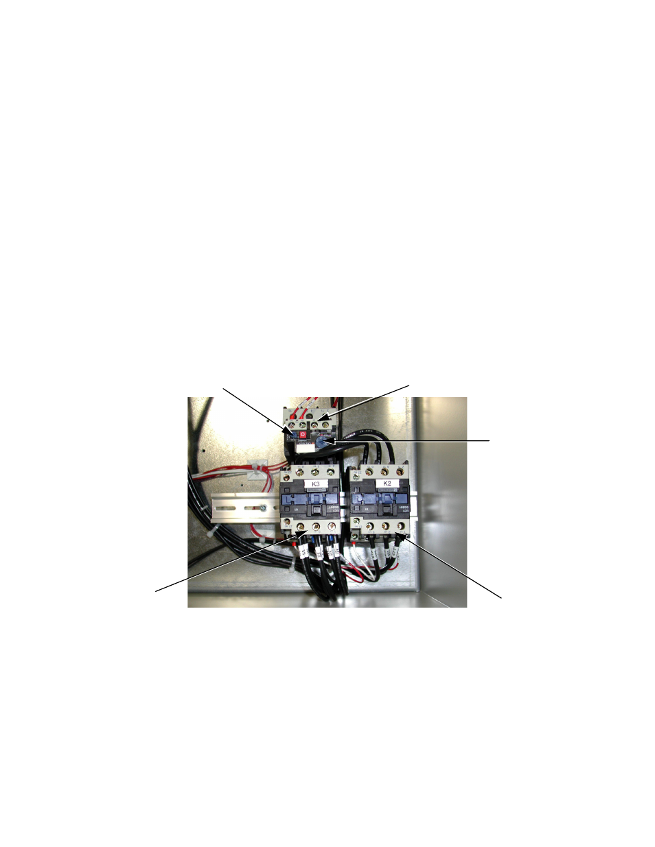
The OLR is mounted to the contactor assembly or back panel (depending on rating), just above the Bypass contactor.
See Figure 4.1. Electrically on the output power side of the Bypass unit, the adjustable thermal OLR provides overload
protection for the motor in both the Drive and Bypass operating modes. The OLR is set up in the factory to be a
manual reset device, requiring operator attention if an overload trip-out is experienced.
Fig 4.1 Typical Motor Overload and Contactors
Adjustment Dial
Bypass Contactor
OverLoad Relay
Output Contactor
Reset Button